 |
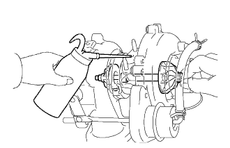
If replacing the turbocharger, add 20 cm3 (1.2 cu in.) of fresh oil into the turbocharger oil inlet hole and turn the turbine wheel by hand to spread oil to the bearing.
TURBOCHARGER > INSTALLATION |
| 1. TEMPORARILY TIGHTEN TURBOCHARGER SUB-ASSEMBLY |
|
If replacing the turbocharger, add 20 cm3 (1.2 cu in.) of fresh oil into the turbocharger oil inlet hole and turn the turbine wheel by hand to spread oil to the bearing.
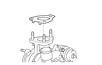 |
Install a new turbo to exhaust manifold gasket as shown in the illustration.
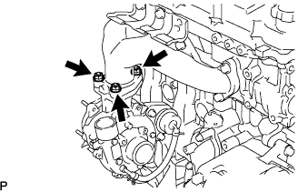 |
Temporarily tighten the turbocharger assembly with the 3 nuts to exhaust manifold.
| 2. TEMPORARILY TIGHTEN TURBO OIL INLET PIPE SUB-ASSEMBLY |
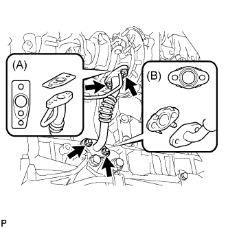 |
Install a new turbo oil inlet gasket (A) and an outlet gasket (B) and temporarily tighten the turbo inlet pipe with the 2 bolts and 2 nuts.
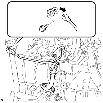 |
Install a new gasket and temporarily tighten the turbo inlet pipe with the union bolt.
| 3. TEMPORARILY TIGHTEN TURBOCHARGER STAY |
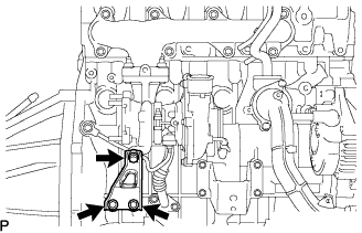 |
Temporarily tighten the turbocharger stay with the 3 bolts.
| 4. FULLY TIGHTEN TURBOCHARGER SUB-ASSEMBLY |
Tighten the turbocharger with the 3 nuts to align the turbocharger and turbo oil inlet pipe.
Tighten the turbocharger stay.
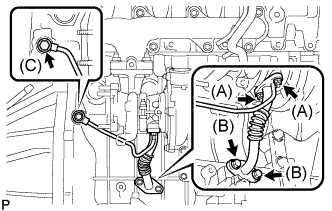 |
Tighten the turbo oil inlet pipe.
| 5. INSTALL TURBINE OUTLET ELBOW |
Install a new gasket to the turbocharger.
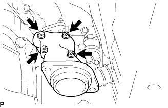 |
Install the turbine outlet elbow with 4 new bolts.
| 6. INSTALL EXHAUST PIPE ASSEMBLY FRONT (for Long Wheelbase) |
Inspect the compression spring.
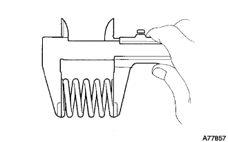 |
Using vernier calipers, measure the free length of the compression springs.
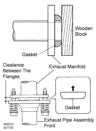 |
Install the gasket.
Fully insert a new gasket to the exhaust manifold by hand.
Using a wooden block, uniformly strike the gasket so that the gasket and exhaust manifold are properly fit.
Connect the exhaust pipe support, and install the exhaust pipe assembly front with the 4 bolts, 2 compression springs and 2 nuts.
| 7. INSTALL EXHAUST PIPE ASSEMBLY FRONT (for Super Long Wheelbase) |
Inspect the compression spring.
|
Using vernier calipers, measure the free length of the compression springs.
|
Install the gasket.
Fully insert a new gasket to the exhaust manifold by hand.
Using a wooden block, uniformly strike the gasket so that the gasket and exhaust manifold are properly fit.
Connect the exhaust pipe support, and install the exhaust pipe assembly front and a new gasket with the 4 bolts, 2 compression springs and 2nuts.
| 8. INSTALL TURBO WATER PIPE SUB-ASSEMBLY NO.2 (for Water Cooled Turbocharger) |
Install a new gasket onto the turbocharger.
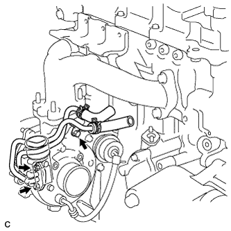 |
Install the turbo water pipe No.2 with the bolt and 2 nuts to the turbocharger.
| 9. INSTALL WATER BY-PASS PIPE SUB-ASSEMBLY NO.2 |
Water cooled turbocharger (w/ heater)
Install a new gasket onto the cylinder block.
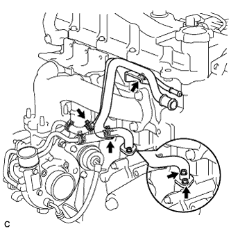 |
Install the water by-pass pipe No.2 with the bolt and 2 nuts.
Connect the 2 water hoses with the 2 clips.
Connect the water by-pass hose No.3 with the clip.
Connect the heater water inlet hose with the clip.
Water cooled turbocharger (w/o heater)
Install a new gasket onto the cylinder block.
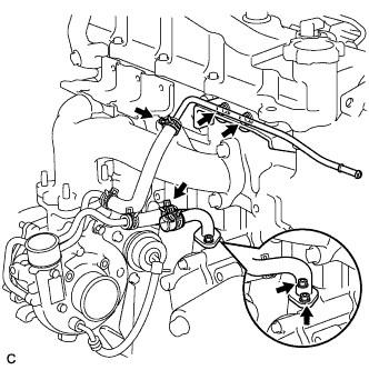 |
Install the water by-pass pipe No.2 with the 2 nuts.
Install the turbo water pipe No.2 with the 2 bolts.
Connect the 2 water hoses with the 2 clips.
Connect the water by-pass hose No.3 with the clip.
Air cooled turbocharger (w/o heater)
Install a new gasket onto the cylinder block.
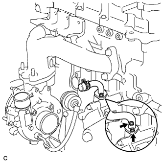 |
Install the water by-pass pipe No.2 with the 2 nuts.
| 10. INSTALL COMPRESSOR ELBOW STAY |
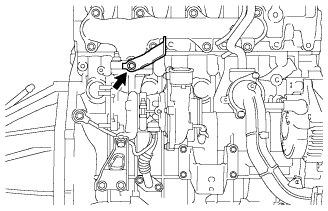 |
Install the compressor elbow stay with the bolt.
| 11. INSTALL COMPRESSOR OUTLET ELBOW |
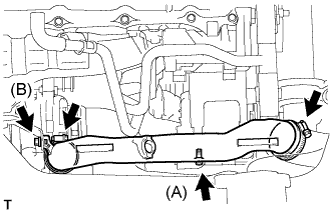 |
Install the compressor outlet elbow with the 2 bolts and 2 clamps.
| 12. INSTALL AIR CLEANER HOSE ASSEMBLY |
Install the air cleaner hose assembly with the clamp.
| 13. INSTALL AIR TUBE ASSEMBLY |
Install the air tube assembly with the 2 clamps and 2 bolts.
| 14. INSTALL VENTILATION PIPE |
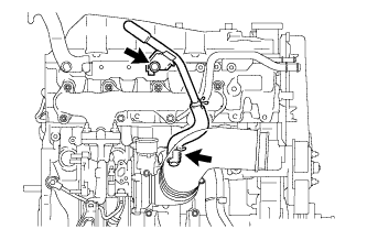 |
Install the ventilation pipe with the bolt and clip.
| 15. INSTALL COMPRESSOR BRACKET (w/ Air Conditioning) |
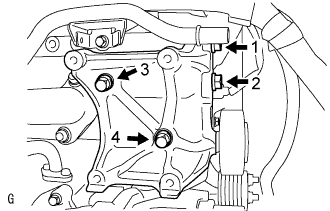 |
Temporarily install the compressor bracket with the 4 bolts.
Install the compressor bracket by tightening the 4 bolts as shown in the illustration.
| 16. INSTALL COMPRESSOR AND MAGNETIC CLUTCH (W/ AIR CONDITIONING) |
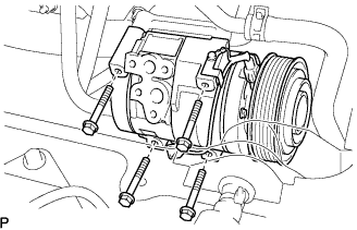 |
Install the compressor and magnetic clutch with the 4 bolts.
| 17. INSTALL FAN AND GENERATOR V BELT |
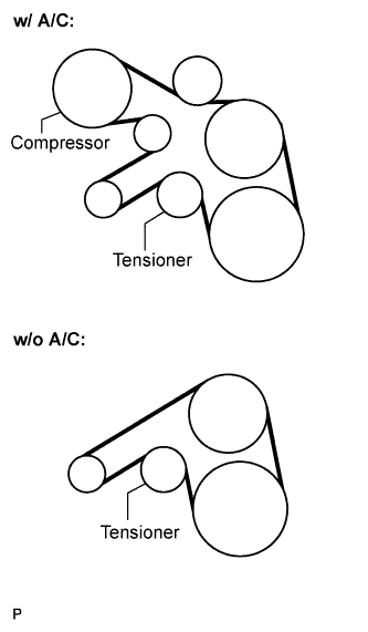 |
Install the drive belt by rotating the tensioner pulley in clockwise direction with the pulley set bolt of the tensioner.
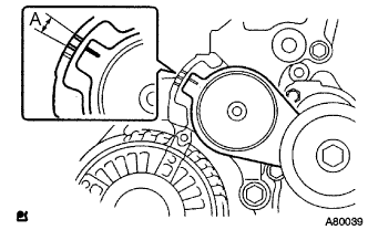 |
Make sure that the indicator mark of the tensioner is within range A.
| 18. ADD ENGINE COOLANT |
Firmly tighten the drain plugs and fill the radiator reserve tank assembly with coolant to the top of the inlet.
Loosen the bleeder plug of outlet housing.
When air is bled and the coolant drains out, firmly install the bleeder plug.
Add coolant up to the B line mark in the radiator reserve tank assembly and install the radiator cap.
| Condition | Capacity |
| w/ rear heater | 17.0 liters (18.0 US qts, 15.0 imp. qts) |
| w/o rear heater | 15.0 liters (15.9 US qts, 13.2 imp. qts) |
Warm up the engine.
After the engine cools down check that the coolant level is between the LOW and FULL level marks.
| 19. CONNECT CABLE TO NEGATIVE BATTERY TERMINAL |
| 20. INSTALL BATTERY SERVICE HOLE COVER (W/ SUB BATTERY) |
| 21. CHECK FOR ENGINE COOLANT LEAKS |
| 22. INSTALL FENDER APRON MUDGUARD SEAL RH |
| 23. INSTALL ENGINE SERVICE HOLE SUB COVER SUB-ASSEMBLY |
Install the engine service hole sub cover with the 5 bolts.
| 24. INSTALL FRONT SEAT ASSEMBLY RH (for Hi-back Seat Type) |
Perform the same procedure as above on the opposite side.
| 25. INSTALL FRONT SEAT ASSEMBLY RH (for Low-back Seat Type) |
Perform the same procedure as above on the opposite side.
| 26. INSTALL FRONT DOOR SCUFF PLATE RH |
| 27. INSTALL ENGINE UNDER COVER NO.2 (w/ Engine Under Cover No.2) |
Install the engine under cover No.2 together with the engine side under cover LH and engine side under cover RH (for Wide Body).
| 28. INSTALL ENGINE UNDER COVER NO.1 (w/ Engine Under Cover No.1) |
| 29. PERFORM INITIALIZATION |