 |
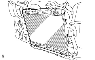
Install the radiator assembly to the vehicle.
- NOTICE:
- Do not drop the radiator assembly.
RADIATOR > INSTALLATION |
| 1. INSTALL RADIATOR ASSEMBLY |
|
Install the radiator assembly to the vehicle.
| 2. INSTALL FAN SHROUD NO.2 |
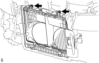 |
Install the fan shroud No.2 with the 2 bolts.
| 3. INSTALL FAN SHROUD |
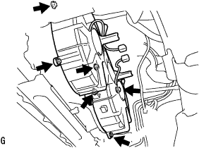 |
Install the fan shroud with the 6 bolts.
Connect the 2 reserve tank hoses.
Connect the 4 radiator hoses.
| 4. CONNECT OIL TUBE (for Automatic Transmission) |
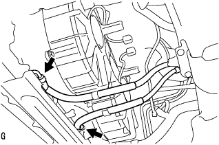 |
Connect the 2 oil tubes to the radiator assembly.
| 5. INSTALL COOLING FAN ECU |
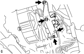 |
Install the cooling fan ECU with the 2 bolts and 2 nuts.
| 6. INSTALL RADIATOR SUPPORT UPPER |
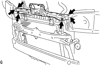 |
Install the radiator support upper with the 6 bolts.
| 7. INSTALL WINDSHIELD WASHER MOTOR AND PUMP ASSEMBLY |
Install the windshield washer motor and pump assembly with the 2 bolts.
| 8. INSTALL RADIATOR RESERVE TANK ASSEMBLY |
Install the radiator reserve tank assembly with the bolt.
| 9. INSTALL INTERCOOLER ASSY |
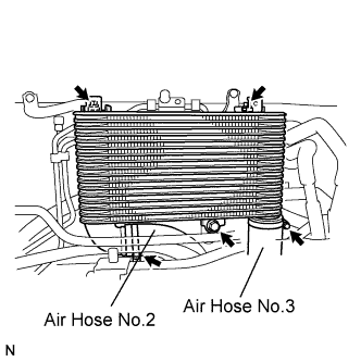 |
Temporarily install the intercooler assembly with the 3 bolts.
Connect the air hose No.2, and tighten the clamp.
Connect the air hose No.3, and tighten the clamp.
Tighten the intercooler assembly.
| 10. INSTALL HOOD LOCK ASSEMBLY |
Install the hood lock cable assembly to the hood lock assembly.
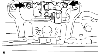 |
Install the hood lock assembly with the 2 bolts.
| 11. INSTALL W/RECEIVER CONDENSER ASSEMBLY (w/ Air Conditioning) |
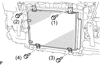 |
Install the w/ receiver condenser assembly with the 4 bolts.
| 12. INSTALL COOLER REFRIGERANT LIQUID PIPE A (w/ Air Conditioning) |
Remove the attached vinyl tape from the pipe and the connecting part of the cooler condenser assembly.
Sufficiently apply compressor oil to a new O-ring and the fitting surface of the pipe joint.
Install the O-ring on the cooler refrigerant liquid pipe A.
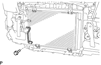 |
Install the cooler refrigerant liquid pipe A on the cooler condenser assembly with the bolt.
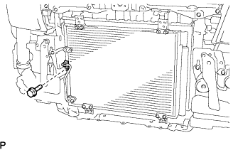 |
Install the clamp with the bolt.
| 13. INSTALL COOLER REFRIGERANT DISCHARGE PIPE A (w/ Air Conditioning) |
Remove the attached vinyl tape from the pipe and the connecting part of the cooler condenser assembly.
Sufficiently apply compressor oil to a new O-ring and the fitting surface of the pipe joint.
Install the O-ring on the cooler refrigerant discharge pipe A.
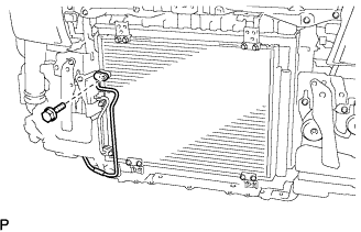 |
Install the cooler refrigerant discharge pipe A on the cooler condenser assembly with the bolt.
| 14. INSTALL FRONT BUMPER REINFORCEMENT |
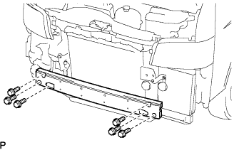 |
Install the front bumper reinforcement with the 6 bolts.
| 15. INSTALL FRONT FLOOR CROSS MEMBER REINFORCEMENT SUB-ASSEMBLY RH |
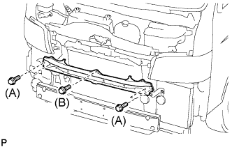 |
Install the front floor cross member reinforcement sub-assembly with the 5bolts.
| 16. INSTALL HOOD LOCK SUPPORT BRACE SUB-ASSEMBLY |
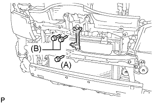 |
Install the hood lock support brace sub-assembly with the 3 bolts.
| 17. INSTALL AIR INLET DUCT NO.1 |
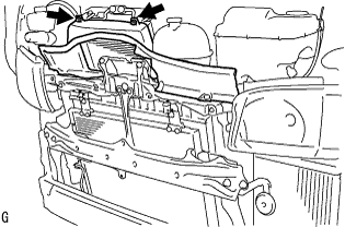 |
Install the air inlet duct No.1 and air inlet duct No.2 with the 7clamps and 2 bolts.
| 18. INSTALL FRONT BUMPER |
| 19. INSTALL STEP PLATE COVER RH |
| 20. INSTALL STEP PLATE COVER LH |
| 21. INSTALL RADIATOR GRILLE |
| 22. ADD ENGINE COOLANT |
Firmly tighten the drain plugs and fill the radiator reserve tank assembly with coolant to the top of the inlet.
Loosen the bleeder plug of outlet housing.
When air is bled and the coolant drains out, firmly install the bleeder plug.
Add coolant up to the B line mark in the radiator reserve tank assembly and install the radiator cap.
| Condition | Capacity |
| w/ rear heater | 17.0 liters (18.0 US qts, 15.0 imp. qts) |
| w/o rear heater | 15.0 liters (15.9 US qts, 13.2 imp. qts) |
Warm up the engine.
After the engine cools down check that the coolant level is between the LOW and FULL level marks.
| 23. CHARGE REFRIGERANT (w/ Air Conditioning) |
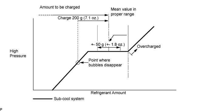
Perform vacuum purging using a vacuum pump.
Charge with refrigerant HFC-134a (R134a).
| 24. WARM UP ENGINE |
Warm up the engine at less than 1,850 rpm for 2 minutes or more after charging refrigerant.
| 25. CHECK FOR ENGINE COOLANT LEAKS |
Fill the radiator with coolant and attach a radiator cap tester to the radiator.
Warm up the engine.
Using a radiator cap tester, increase the pressure inside the radiator to 137 kPa (1.4 kgf/cm2, 19.9 psi), and check that the pressure does not drop.
| 26. CHECK FOR LEAKAGE OF REFRIGERANT (w/ Air Conditioning) |
After recharging refrigerant gas, check for leakage of refrigerant gas using a halogen leak detector.
Carry out the test under the following conditions:
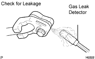 |
Using a gas leak detector, check for leakage of the refrigerant line.
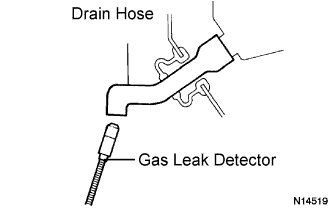 |
Bring the gas leak detector close to the drain hose with the detector's power off.
If a gas leak is not detected on the drain hose, remove the blower motor control from the cooling unit. Insert the gas leak detector sensor into the unit and perform the test.
Disconnect the pressure switch connector and leave it for approximately 20 minutes. Bring the gas leak detector close to the pressure switch and perform the test.