 |
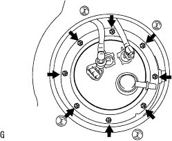
Install the fuel pump assembly and fuel bent tube set plat with the 8 bolts.
- Torque:
- 4.0 N*m{ 41 kgf*cm , 35 in.*lbf }
FUEL TANK > INSTALLATION |
| 1. INSTALL FUEL PUMP ASSEMBLY |
|
Install the fuel pump assembly and fuel bent tube set plat with the 8 bolts.
| 2. CONNECT FUEL TANK WIRE |
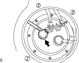 |
Connect the fuel tank wire connector to the fuel pump assembly.
| 3. CONNECT FUEL TANK MAIN TUBE SUB-ASSEMBLY |
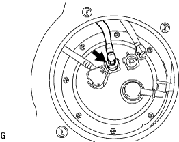 |
connect the fuel tank main tube with the tube joint clip.
| 4. CONNECT FUEL TANK RETURN TUBE |
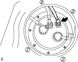 |
Connect the fuel tank return tube with the tube joint clip.
| 5. CONNECT FUEL EVAPORATION TUBE SUB-ASSEMBLY NO.1 |
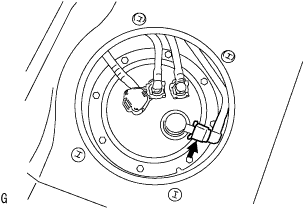 |
Match the axis of the connector with the axis of the pipe, and push into the connector until the connector makes a 'click' sound. In case that the connection is tight, apply a small amount of fresh engine oil to the tip of the pipe.
| 6. INSTALL FUEL TANK ASSEMBLY |
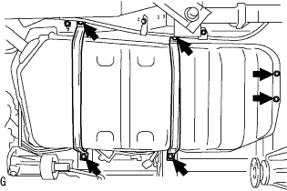 |
Using the transmission jack, install the 2 fuel tank band sub-assemblies and fuel tank assembly with the 6 bolts.
Connect the parking brake cable No.3 with the bolt.
| 7. CONNECT FUEL TANK HOSE NO.3 |
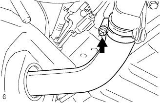 |
Connect the fuel hose No.3, and tighten the clamp bolt.
| 8. CONNECT FUEL TANK BREATHER TUBE SUB-ASSEMBLY NO.1 |
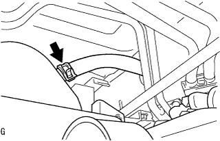 |
Connect the fuel tank breather tube and clip.
| 9. CONNECT FUEL TANK MAIN TUBE SUB-ASSEMBLY |
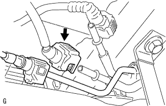 |
Connect the fuel tank main tube sub-assembly and clamp. (Click here)
| 10. CONNECT FUEL TANK RETURN TUBE |
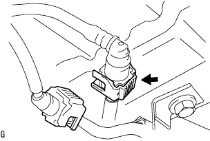 |
Connect the fuel return tube sub-assembly. (Click here)
| 11. CONNECT FUEL EVAPORATION TUBE SUB-ASSEMBLY NO.1 |
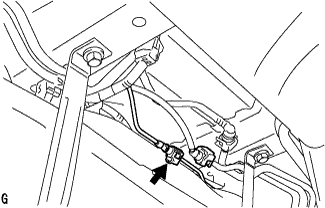 |
Disconnect fuel evaporation tube sub-assembly. (Click here)
| 12. CONNECT FUEL TANK WIRE |
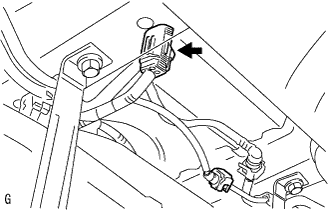 |
Connect the fuel tank wire.
| 13. INSTALL PROPELLER SHAFT ASSEMBLY |
| 14. BLEED FUEL LINE |
Check that the battery voltage is above 12 V.
Disconnect the negative terminal cable from the battery.
Disconnect the fuel hose from the fuel filter assembly.
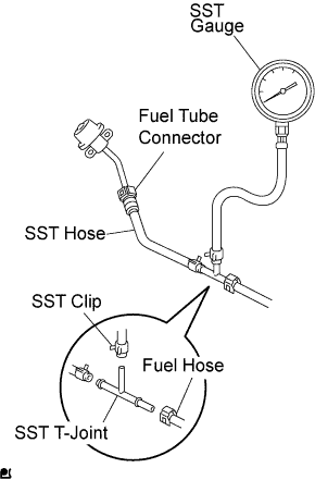 |
Install SST (pressure gauge) using SSTs and a fuel tube connector as shown in the illustration.
Wipe off any splattered gasoline.
Reconnect the negative terminal cable to the battery.
Connect the intelligent tester to the DLC3 (See step 1 in check fuel pump operation).
Measure the fuel pressure.
Disconnect the intelligent tester from the DLC3.
Stop the engine.
Measure the fuel pressure at idle.
Stop the engine.
Check that the fuel pressure remains as specified for 5 minutes after the engine has stopped.
After checking fuel pressure, disconnect the negative terminal cable from the battery and carefully remove the SST to prevent gasoline from splashing.
Connect the fuel hose to the fuel filter assembly.
Reconnect the negative terminal cable to the battery.
Check for fuel leakage.
| 15. CHECK FOR FUEL LEAKS |
When using the intelligent tester
Connect the intelligent tester to the DLC3.
Turn the ignition switch to the on position and intelligent tester main switch ON.
Select the Active Test mode on the intelligent tester.
When not using the intelligent tester.
|
Disconnect the fuel pump connector.
Using a service wire, connect terminals FP and +B of the relay block.
Turn the ignition switch to the ON position, and check that the fuel pump operates.
Check that there are no fuel leaks anywhere on the fuel system after doing maintenance.
Check that the pulsation damper screw rises up when the fuel pump operates.
If operation is not as specified, check the following parts:
Turn the ignition switch off.
Disconnect the intelligent tester from the DLC3.