 |
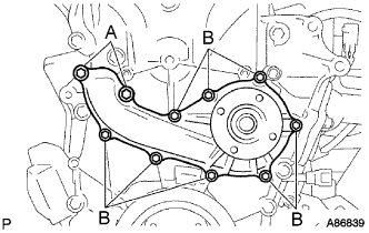
Install a new gasket and the water pump assembly with the 10 bolts.
- Torque:
- Bolt (A):
- 21 N*m{ 214 kgf*cm , 15 ft.*lbf }
- Bolt (B):
- 9.0 N*m{ 92 kgf*cm , 80 in.*lbf }
WATER PUMP > INSTALLATION |
| 1. INSTALL WATER PUMP ASSEMBLY |
|
Install a new gasket and the water pump assembly with the 10 bolts.
| 2. INSTALL VANE PUMP ASSEMBLY |
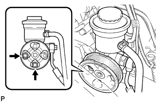 |
Install the vane pump with the 2 bolts.
Connect the PS fluid pressure switch connector.
| 3. INSTALL V-RIBBED BELT TENSIONER ASSEMBLY |
| 4. INSTALL GENERATOR ASSEMBLY |
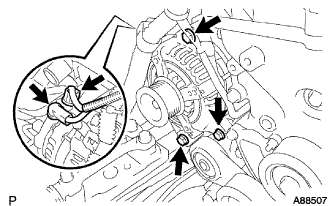 |
Install the generator assembly with the 3 bolts.
Install the generator wire with the nut to terminal B.
Install the terminal cap.
Connect the generator connector.
| 5. INSTALL FAN PULLEY |
Install the fan spacer and fan pulley with the 4 nuts.
| 6. INSTALL FAN AND GENERATOR V BELT |
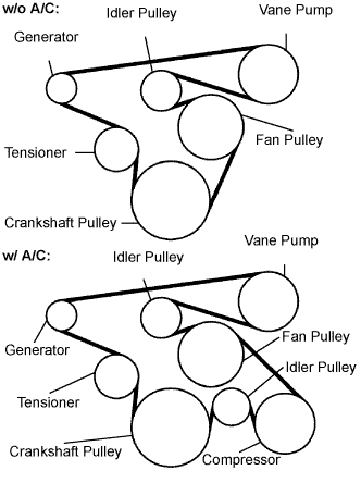 |
Install the drive belt to the pulleys except the drive belt tensioner pulley.
Use the hexagon-shaped part indicated by the arrow in the illustration to move the tensioner pulley downward and then install the drive belt to the tensioner pulley.
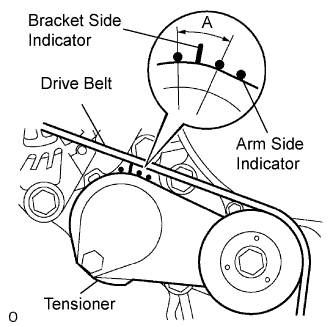 |
After a new belt has been installed, check that the tensioner indicator mark is within range A shown in the illustration.
| 7. INSTALL INTAKE AIR CONNECTOR |
Temporarily install the intake air connector to the throttle body assembly.
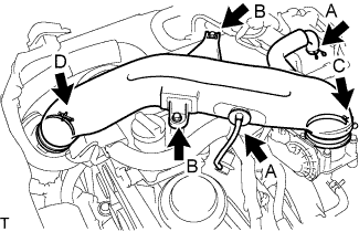 |
Connect the ventilation hose No.2 and the vacuum hose. (A)
Install the intake air connector with the 2 bolts. (B)
Tighten the 2 hose clamp bolts. (C)
Tighten the 2 hose clamp bolts. (D)
| 8. INSTALL ENGINE SERVICE HOLE SUB COVER SUB-ASSEMBLY |
Install the engine service hole sub cover with the 5 bolts.
| 9. INSTALL FRONT SEAT ASSEMBLY RH (for Hi-back Seat Type) |
| 10. INSTALL FRONT SEAT ASSEMBLY RH (for Low-back Seat Type) |
| 11. INSTALL FRONT DOOR SCUFF PLATE RH |
| 12. CONNECT CABLE TO NEGATIVE BATTERY TERMINAL |
| 13. ADD ENGINE COOLANT |
Firmly tighten the drain plugs and fill the reservoir tank with coolant to the top of the inlet.
Remove the 2-way that is located near the throttle body.
When air is bled and the coolant drains out, firmly install the 2-way.
Add coolant up to the B line mark in the reservoir tank and install the radiator cap.
| Condition | Capacity |
| w/ rear heater | 15.0 liters (15.8 US qts, 13.2 lmp. qts) |
| w/o rear heater | 13.0 liters (13.7 US qts, 11.4 lmp. qts) |
Warm up the engine.
After the engine cools down, check that the coolant level is between the LOW and FULL level marks.
| 14. CHECK FOR ENGINE COOLANT LEAKS |
Fill the radiator with coolant and attach a radiator cap tester to the radiator.
Warm up the engine.
Using a radiator cap tester, increase the pressure inside the radiator to 137 kPa (1.4 kgf/cm2, 19.9 psi), and check that the pressure does not drop.
| 15. INSTALL ENGINE UNDER COVER NO.1 |
| 16. PERFORM INITIALIZATION |