 |
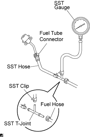
Install SST (pressure gauge) using SSTs and a fuel tube connector as shown in the illustration.
- SST
- 09268-41048
(09268-41120, 90467-13001, 95336-08070, 09268-41500)
FUEL INJECTOR > REMOVAL |
| 1. DISCHARGE FUEL SYSTEM PRESSURE |
Check that the battery voltage is above 12 V.
Disconnect the negative terminal cable from the battery.
Disconnect the fuel hose from the fuel filter assembly.
|
Install SST (pressure gauge) using SSTs and a fuel tube connector as shown in the illustration.
Wipe off any splattered gasoline.
Reconnect the negative terminal cable to the battery.
Connect the intelligent tester to the DLC3 (See step 1 in check fuel pump operation).
Measure the fuel pressure.
Disconnect the intelligent tester from the DLC3.
Stop the engine.
Measure the fuel pressure at idle.
Stop the engine.
Check that the fuel pressure remains as specified for 5 minutes after the engine has stopped.
After checking fuel pressure, disconnect the negative terminal cable from the battery and carefully remove the SST to prevent gasoline from splashing.
Connect the fuel hose to the fuel filter assembly.
Reconnect the negative terminal cable to the battery.
Check for fuel leakage.
| 2. DISCONNECT BATTERY NEGATIVE CABLE |
| 3. DRAIN ENGINE COOLANT |
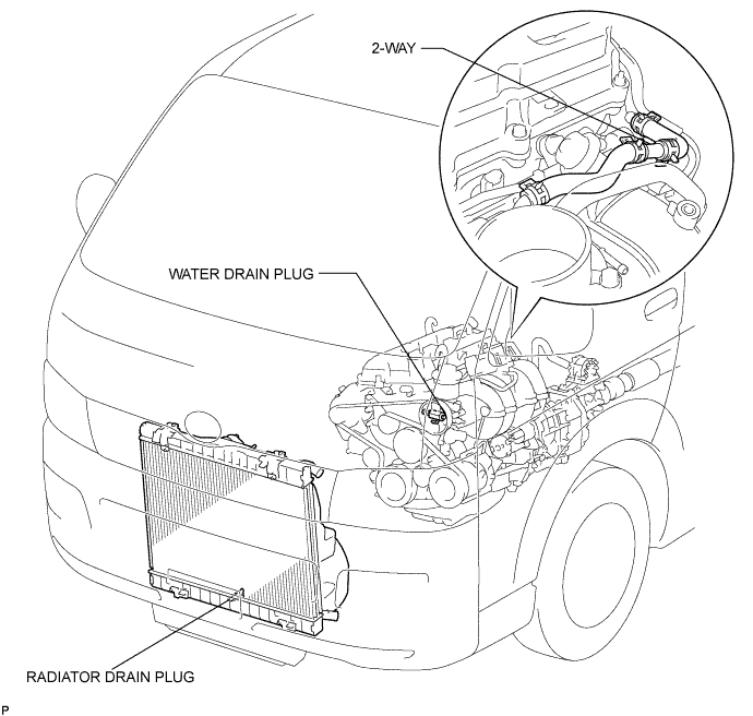
Remove the radiator cap.
Loosen the radiator drain plug and a cylinder block drain plug. Then drain the coolant.
| 4. REMOVE FRONT SEAT ASSEMBLY RH (for Hi-back Seat Type) |
| 5. REMOVE FRONT SEAT ASSEMBLY RH (for Low-back Seat Type) |
| 6. REMOVE FRONT DOOR SCUFF PLATE RH |
| 7. REMOVE ENGINE SERVICE HOLE SUB COVER SUB-ASSEMBLY |
Roll up the carpet, and remove the 5 bolts and engine service hole sub cover.
| 8. REMOVE INTAKE AIR CONNECTOR |
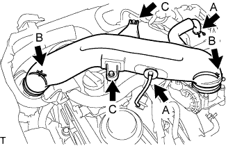 |
Disconnect the ventilation hose No.2 and the vacuum hose.(A)
Loosen the 2 hose clamp bolts.(B)
Remove the 2 bolts, then remove the intake air connector.(C)
| 9. REMOVE THROTTLE BODY ASSEMBLY |
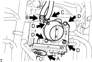 |
Disconnect the throttle motor connector.(A)
Disconnect the water by-pass hose.(B)
Disconnect the water by-pass hose No.2.(C)
Remove the 2 bolts and 2 nuts, then remove the throttle body assembly.(D)
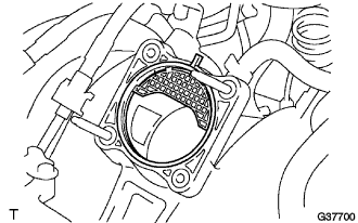 |
Remove the gasket from the intake manifold.
| 10. DISCONNECT FUEL HOSE |
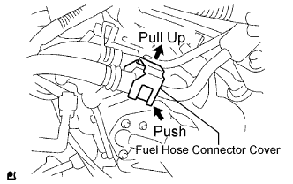 |
Pull the fuel hose connector cover up to release the lock. (Click here)
Disengage the fuel connector to disconnect the fuel hose. (Click here)
| 11. REMOVE FUEL DELIVERY PIPE SUB-ASSEMBLY |
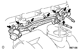 |
Disconnect the fuel hoses.
Disconnect the 4 injector connectors.
Remove the 2 bolts O-ring and fuel pulsation damper assembly.
Remove the 2 bolts and delivery pipe together with the 4 injectors.
Remove the delivery pipe spacers.
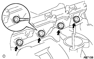 |
Using a screwdriver, pry out the 4 spacers from the cylinder head.
| 12. REMOVE INJECTOR ASSEMBLY |
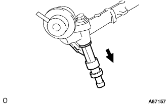 |
Pull out the 4 injectors from the delivery pipe.
Remove the O-rings from the injectors.