FUEL INJECTOR > INSTALLATION |
| 1. INSTALL INJECTOR ASSEMBLY |
|
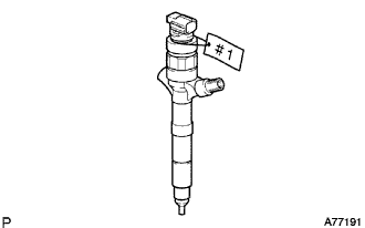 |
Put tags with cylinder numbers (#1 to #4) onto the new injector assembly in order to make sure of the right combinations with the right cylinders.
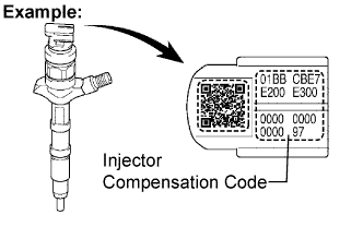
Register the injector compensation code manually (Click here).
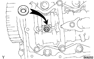 |
Install a new injection nozzle sheet to the cylinder head.
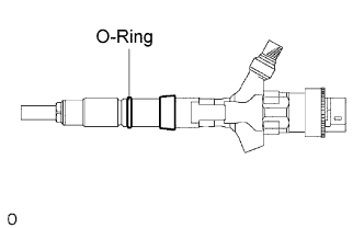 |
Install a new O-ring.
Install the injector assembly to each cylinder referring to the tags with cylinder numbers (#1 to #4).
Temporarily install the 4 injection pipes.
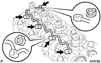 |
Apply a light coat of engine oil to the 4 hollow screws and union bolt.
Temporarily install the nozzle leakage pipe assembly and 5 new nozzle leakage pipe gaskets and tighten the 4 hollow screws, union bolt by hand until them cannot turn.
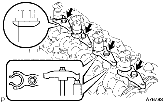 |
Install the 4 nozzle holder clamps and 4 new washers with the 4 bolts as show in the illustration.
Tighten the new washers and 4 bolts.
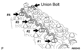 |
Tighten the 4 hollow screws from #1 to #4 in order.
Tighten the union bolt.
Remove the injection pipe No.1, No.2, No.3 and No.4.
| 2. CHECK NOZZLE LEAKAGE PIPE LEAK |
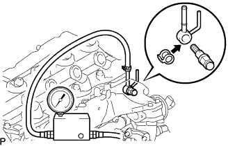 |
Using SST, install the nozzle leakage pipe No.2 and a new gasket.
| Nozzle leakage pipe No.2 | 23762 - 27010 |
| Gasket | 90904 - 30012 |
Using SST (turbo charge pressure gauge), set the SST to the leakage pipe No.2 and maintain 250 kPa (2.5 kgf/cm2, 37 psi) of pressure for 60 seconds to check that there are no leaks from the nozzle leakage pipe assembly.
Remove the SST, nozzle leakage pipe assembly No.2.
| 3. INSTALL NOZZLE LEAKAGE PIPE ASSEMBLY NO.2 |
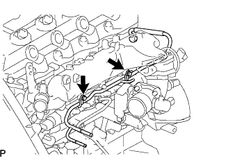 |
Temporarily install the nozzle leakage pipe assembly No.2 with the 2 bolts.
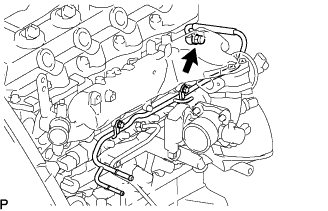 |
Install the check valve nozzle leakage pipe assembly No.2 and a new gasket.
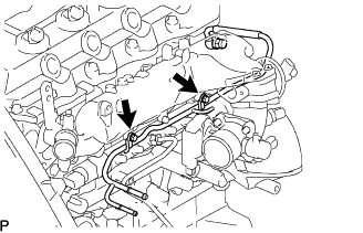 |
Tighten the 2 bolts.
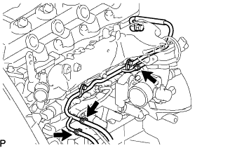 |
Install the 3 fuel hoses on the nozzle leakage pipe assembly No.2.
| 4. INSTALL CYLINDER HEAD COVER SUB-ASSEMBLY |
Remove old seal packing (FIPG) from the cylinder head.
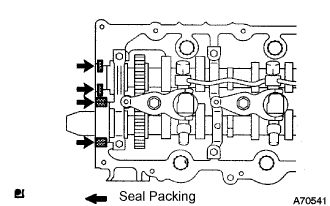 |
Apply a seal packing to the specific places described in the illustration.
Install the cylinder head cover with 10 bolts and 2 nuts.
Connect the ventilation hose.
Install a new nozzle holder seal.
| 5. INSTALL INJECTION PIPE |
Install the injection pipes.
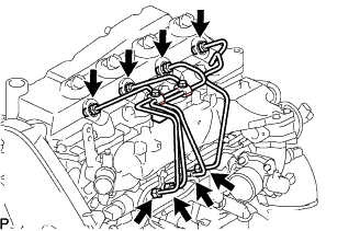 |
Temporarily install the 4 injection pipes.
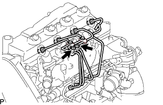 |
Install the injection pipe clamp No.3 in 2 nuts.
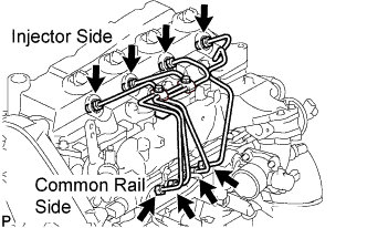 |
Fasten the union sequentially, from the injection pipe common rail to the injector, using SST.
| 6. INSTALL OIL LEVEL GAGE GUIDE |
Install a new O-ring to the oil level gauge guide.
Apply a light coat of engine oil to the O-ring.
Install the oil level gauge guide with the bolt.
Install the oil level gauge.
| 7. INSTALL INTAKE AIR CONNECTOR (w/o EGR Valve) |
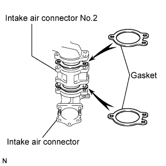 |
Temporarily install 2 new gaskets and intake air connector No.2 to the intake air connector.
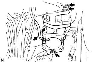 |
Temporarily tighten the intake air connector assembly with the bolt and 2 nuts.
Tighten the manifold stay with the bolt.
Tighten the intake air connector with the bolt and 2 nuts.
Install the vacuum hose to the intake air connector.
| 8. TEMPORARILY TIGHTEN ELECTRIC EGR CONTROL VALVE ASSEMBLY (w/ EGR Valve) |
Temporarily tighten the EGR valve assembly with the sensor.
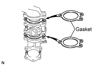 |
Install 2 new gaskets and the EGR valve to the intake air connector as shown in the illustration.
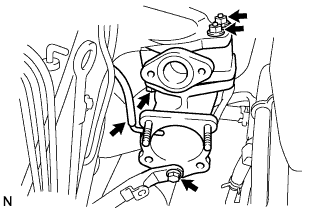 |
Temporarily tighten the intake air connector with EGR valve assembly to the intake manifold with the bolt and the 2 nuts.
Install the vacuum hose to the intake air connector.
Temporarily tighten the manifold stay with the bolt.
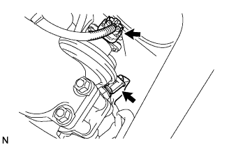 |
Connect the EGR valve position sensor connector.
Connect the intake air temperature sensor connector.
Install the vacuum regulating valve.
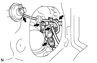 |
Install the vacuum regulating valve with the 2 bolts.
Connect the 2 vacuum hoses and the regulating valve connector.
| 9. INSTALL EGR PIPE SUB-ASSEMBLY NO.1 (w/ EGR Valve) |
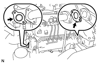 |
Install the 2 gaskets to the cylinder head and EGR pipe sub-assembly as shown in the illustration.
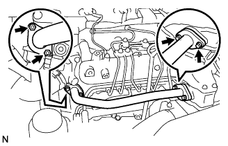 |
Install the EGR pipe sub-assembly with the 2 bolts and 2 nuts.
Tighten the intake air connector with the bolt and the 2 nuts.
Tighten the manifold stay.
| 10. REMOVE EGR PIPE SUB-ASSEMBLY NO.1 (w/ EGR Valve) |
Remove the 3 bolts, the 2 nuts, and the EGR pipe sub-assembly.
Remove the 2 gaskets.
| 11. INSTALL DIESEL THROTTLE BODY ASSEMBLY |
Install a new gasket to intake air connector.
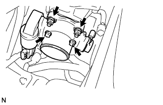 |
Install the throttle body with the 2 bolts and the 2 nuts.
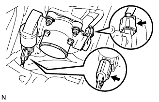 |
Connect the 2 throttle body connectors.
| 12. INSTALL AIR HOSE NO.4 |
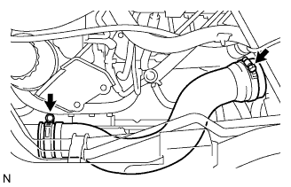 |
Install the air hose No.4 with the 2 clamps.
| 13. INSTALL EGR PIPE SUB-ASSEMBLY NO.1 (w/ EGR Valve) |
|
Install 2 new gaskets to the cylinder head and the EGR pipe sub-assembly No.1 as shown in the illustration.
|
Install the EGR pipe with the 2 bolts and the 2 nuts.
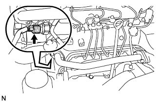 |
Connect the fuel pressure sensor connector.
| 14. CONNECT OIL RETURN HOSE |
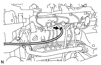 |
Connect the oil return hose with the clip.
| 15. INSTALL VANE PUMP OIL RESERVOIR ASSEMBLY |
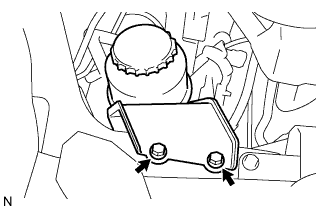 |
Install the vane pump oil reservoir assembly with the 2 bolts.
| 16. INSTALL ENGINE SERVICE HOLE SUB COVER SUB-ASSEMBLY |
Install the engine service hole sub cover with the 5 bolts.
| 17. INSTALL FRONT DOOR SCUFF PLATE RH |
| 18. INSTALL FRONT SEAT ASSEMBLY RH (for Hi-back Seat Type) |
Perform the same procedure as above on the opposite side.
| 19. INSTALL FRONT SEAT ASSEMBLY RH (for Low-back Seat Type) |
Perform the same procedure as above on the opposite side.
| 20. CHECK INJECTOR COMPENSATION CODE |
Check that the injector compensation code registered in the injector assembly installed on each cylinder match the ones registered in the ECM (Click here).
| 21. ADD ENGINE COOLANT |
Firmly tighten the drain plugs and fill the radiator reserve tank assembly with coolant to the top of the inlet.
Loosen the bleeder plug of outlet housing.
When air is bled and the coolant drains out, firmly install the bleeder plug.
Add coolant up to the B line mark in the radiator reserve tank assembly and install the radiator cap.
| Condition | Capacity |
| w/ rear heater | 17.0 liters (18.0 US qts, 15.0 imp. qts) |
| w/o rear heater | 15.0 liters (15.9 US qts, 13.2 imp. qts) |
Warm up the engine.
After the engine cools down check that the coolant level is between the LOW and FULL level marks.
| 22. CHECK FOR ENGINE COOLANT LEAKAGE |
Remove the radiator cap.
Check if there is any excessive deposits of rust or scale around the radiator cap and radiator filler hole. The coolant should be free from oil.
Install the radiator cap.
| 23. BLEED FUEL LINE |
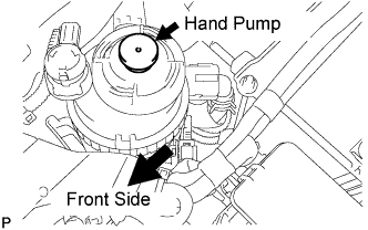 |
Using the hand pump, bleed air from the fuel system until pumping becomes difficult.
| 24. INSTALL ENGINE UNDER COVER NO.1 (w/ Engine Under Cover) |
| 25. DISCONNECT BATTERY NEGATIVE CABLE |
| 26. INSTALL BATTERY SERVICE HOLE COVER |
| 27. CHECK FOR FUEL LEAKS |
PERFORM ACTIVE TEST
Connect the intelligent tester to the DLC3.
Turn the ignition switch on.
Turn the intelligent tester on.
Enter the following menus: Powertrain / ECD / Active Test.
Perform the Active Test.
| Intelligent Tester Display | Test Details | Control Range | Diagnostic Notes |
| Test the Fuel Leak | Pressurizes common rail internal fuel pressure, and checks for fuel leaks | Stop/Start |
|