SLIDE DOOR > ADJUSTMENT |
| 1. INSPECT SLIDE DOOR |
Check that the clearance of areas A to H are within the standard range.
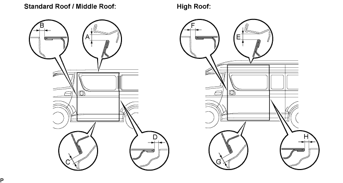
| Area | Measurement | Area | Measurement |
| A | 6.9 +- 1.5 mm (0.272 +- 0.059 in.) | E | 6.4 +- 1.5 mm (0.252 +- 0.059 in.) |
| B | 5.5 +- 1.5 mm (0.217 +- 0.059 in.) | F | 5.5 +- 1.5 mm (0.217 +- 0.059 in.) |
| C | 5.8 +- 1.5 mm (0.228 +- 0.059 in.) | G | 5.8 +- 1.5 mm (0.028 +- 0.059 in.) |
| D | 5.0 +- 1.5 mm (0.197 +- 0.059 in.) | H | 5.0 +- 1.5 mm (0.197 +- 0.059 in.) |
| 2. ADJUST SLIDE DOOR |
Disconnect the cable from negative (-) battery terminal from the battery.
Loosen the 2 bolts from the slide door down male stop (body side).
![]() |
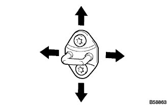
When adjusting the door rear side to side, and the slide door lock striker plate assembly, use a "torx" socket wrench (T40) to loosen the screws until the striker can move. Lightly tap it with a brass bar for adjustment.
![]() |
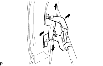
Using a SST, loosen the bolts on the sliding door hinge assembly center to adjust the sliding door rear front and back, up and down.
![]() |
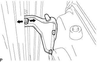
Loosen the nuts on the sliding door lower assembly upper to adjust the sliding door upper front side to side.
![]() |
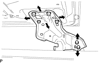
Loosen the bolts on the sliding door lower assembly lower to adjust the sliding door front lower side to side (body side), back and forth and up and down (door side).
Temporarily tighten the 2 bolts on the sliding door down male stopper (body side), completely close the sliding door to confirm the position. Fully tighten the 2 bolts on the sliding door down male stopper (body side).
Connect the negative (-) terminal cable to the battery.
Initialize both systems.
Inspect the SRS warning light.
After completing fitting adjustment, make sure that the electric door lock and the slide door easy closer operate normally.