 |
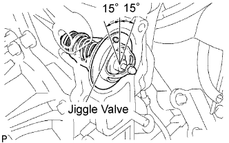
Install the thermostat with the jiggle valve facing up.
- HINT:
- The jiggle valve may be set within 15° on either side of the prescribed position.
THERMOSTAT > INSTALLATION |
| 1. INSTALL THERMOSTAT |
Install a new gasket to the thermostat.
|
Install the thermostat with the jiggle valve facing up.
| 2. INSTALL WATER INLET |
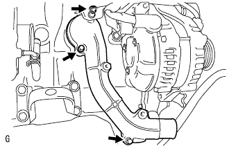 |
Install the water inlet with the 3 bolts.
| 3. CONNECT ENGINE WIRE |
Connect the engine wire to the bracket.
| 4. INSTALL VENTILATION PIPE |
Install the ventilation pipe with the bolt.
| 5. INSTALL COMPRESSOR OUTLET ELBOW |
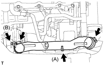 |
Install the compressor outlet elbow with the 2 bolts and 2 clamps.
| 6. INSTALL AIR CLEANER HOSE ASSEMBLY |
Install the air cleaner hose assembly with the clamp.
| 7. INSTALL AIR TUBE ASSEMBLY |
Install the air tube assembly with the 2 clamps and 2 bolts.
| 8. INSTALL COMPRESSOR AND MAGNETIC CLUTCH (w/ Air Conditioning) |
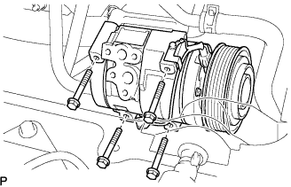 |
Install the compressor and magnetic clutch with the 4 bolts.
| 9. INSTALL FAN AND GENERATOR V BELT |
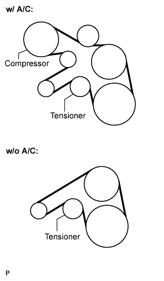 |
Install the drive belt by rotating the tensioner pulley in clockwise direction with the pulley set bolt of the tensioner.
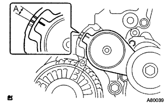 |
Make sure that the indicator mark of the tensioner is within range A.
| 10. INSTALL FENDER APRON MUDGUARD SEAL RH |
| 11. INSTALL ENGINE SERVICE HOLE SUB COVER SUB-ASSEMBLY |
Install the engine service hole sub cover with the 5 bolts.
| 12. INSTALL FRONT DOOR SCUFF PLATE RH |
| 13. INSTALL FRONT SEAT ASSEMBLY RH (for Hi-back Seat Type) |
| 14. INSTALL FRONT SEAT ASSEMBLY RH (for Low-back Seat Type) |
| 15. CONNECT BATTERY NEGATIVE CABLE |
| 16. ADD ENGINE COOLANT |
Firmly tighten the drain plugs and fill the radiator reserve tank assembly with coolant to the top of the inlet.
Loosen the bleeder plug of outlet housing.
When air is bled and the coolant drains out, firmly install the bleeder plug.
Add coolant up to the B line mark in the radiator reserve tank assembly and install the radiator cap.
| Condition | Capacity |
| w/ rear heater | 17.0 liters (18.0 US qts, 15.0 imp. qts) |
| w/o rear heater | 15.0 liters (15.9 US qts, 13.2 imp. qts) |
Warm up the engine.
After the engine cools down check that the coolant level is between the LOW and FULL level marks.
| 17. CHECK FOR ENGINE COOLANT LEAKAGE |
Fill the radiator with coolant and attach a radiator cap tester to the radiator.
Warm up the engine.
Using a radiator cap tester, increase the pressure inside the radiator to 137 kPa (1.4 kgf/cm2, 19.9 psi), and check that the pressure does not drop.
| 18. INSTALL ENGINE UNDER COVER NO.1 |