AIR CONDITIONING SYSTEM > SYSTEM DESCRIPTION |
| GENERAL |
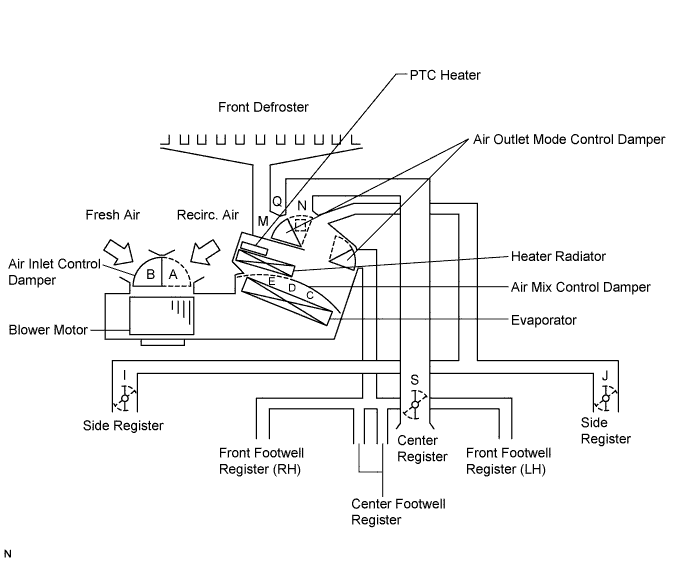
Air Conditioning Unit
Other Equipment
| MODEL POSITION AND DAMPER OPERATION |
| Control Damper | Control Position | Damper Position | Operation | ||
| Air Inlet Control Damper | FRESH | B | Brings in fresh air. | ||
| RECIRC | A | Recirculates internal air. | |||
| Air Mix Control Film Damper | Driver and Front Passenger Side | MAX COOL to MAX HOT (TEMP. SETTING 18 to 32°C (64 to 90°F)) | C, D, E | Varies the mixture ratio of the fresh air and the recirculation air in order to regulate the temperature continuously from HOT to COOL. | |
| Mode Control Film Damper | Driver and Front Passenger Side | FACE | I, J, M, O, S | Air blows out of the front and rear center registers, and side registers. | |
BI - LEVEL | I, J, M, P, S | Air mainly blows out of the front and rear center registers, side registers, and footwell register ducts. | |||
FOOT | I, J, Q, L, S | Air mainly blows out of the front and rear footwell register ducts. In addition, air blows out slightly from the front and side defrosters, and the side registers. | |||
FOOT / DEF | I, J, N, L, S | Air mainly blows out of the front and side defrosters to defrost the windshield. Air also blows out from the front and rear footwell register ducts, and the side registers. | |||
DEF | I, J, N, O, S | Air blows out of the front and side defrosters and side registers to defrost the windshield. | |||
| AIR OUTLETS AND AIRFLOW VOLUME |
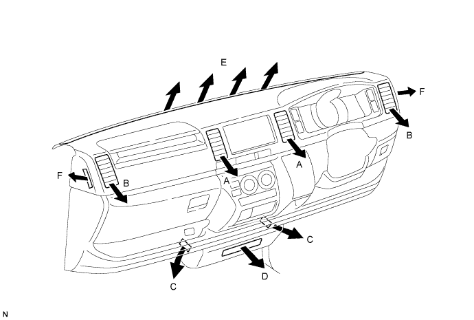
| Air Outlet Mode | A | B | C | D | E | F |
| Center Face | Side Face | Foot | Foot | Center Defroster | Side Defroster | |
| FACE 187BE24 |  | |  | | | |
| BI-LEVEL 187BE25 |  | | |  | | |
| FOOT 187BE26 | | | | | | |
| FOOT/DEF 187BE27 | | | | | | |
| DEF 187BE28 | | | | | | |