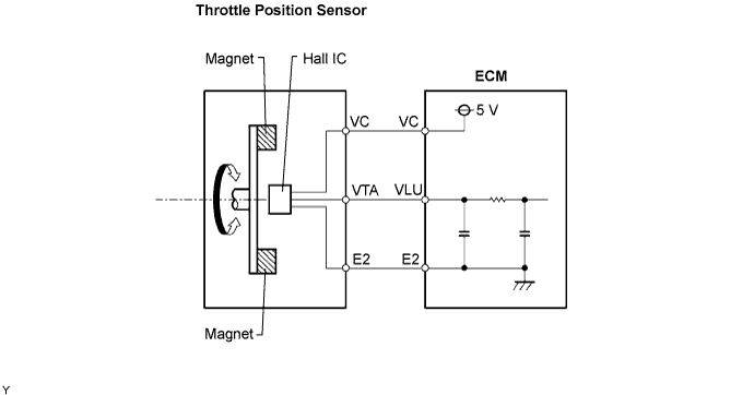
DTC P0120/41 Throttle Pedal Position Sensor / Switch "A" Circuit Malfunction |
DTC P0122/41 Throttle / Pedal Position Sensor / Switch "A" Circuit Low Input |
DTC P0123/41 Throttle / Pedal Position Sensor / Switch "A" Circuit High Input |
| DTC No. | DTC Detection Condition | Trouble Area |
| - | Condition of DTC P0120/41, P0122/41 or P0123/41 continues for 3 seconds (open or short in throttle position sensor circuit) | - |
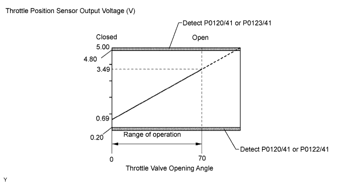
| P0120/41 | Throttle position sensor output (VLU) flutters up and down beyond normal operating range (less than 0.2 V or more than 4.8 V) (1 trip detection logic) |
|
| P0122/41 | Throttle position sensor output (VLU) is less than 0.2 V (1 trip detection logic) |
|
| P0123/41 | Throttle position sensor output (VLU) is more than 4.8 V (1 trip detection logic) |
|
| 1.CHECK HARNESS AND CONNECTOR (THROTTLE POSITION SENSOR - ECM) |
 |
Disconnect the D3 and D1 ECM connectors.
Disconnect the D50 throttle position sensor connector.
Measure the resistance of the wire harness side connectors.
| Tester Connection | Specified Condition |
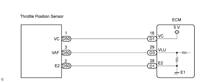
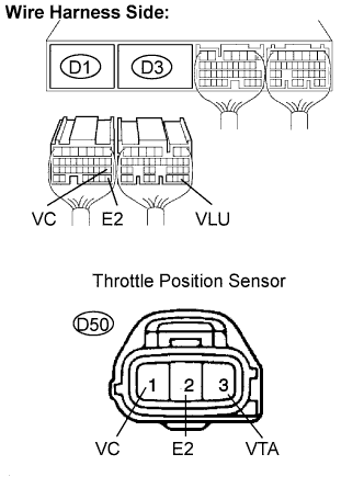
| D1-18 (VC) - D50-1 (VC) | Below 1 Ω |
| D3-29 (VLU) - D50-3 (VTA) | Below 1 Ω |
| D1-28 (E2) - D50-2 (E2) | Below 1 Ω |
| D1-18 (VC) or D50-1 (VC) - Body ground | 10 kΩ or higher |
| D3-29 (VLU) or D50-3 (VTA) - Body ground | 10 kΩ or higher |
| D1-28 (E2) or D50-2 (E2) - Body ground | 10 kΩ or higher |
|
| ||||
| OK | |
 |
| 2.CHECK ECM TERMINAL VOLTAGE (VC TERMINAL) |
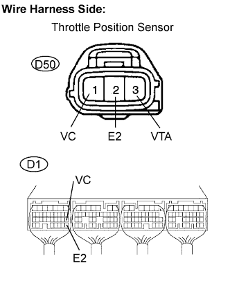 |
Disconnect the D50 sensor connector.
Turn the ignition switch ON.
Measure the voltage of the ECM connector.
| Tester Connection | Specified Condition |
| D1-18 (VC) - D1-28 (E2) | 4.5 to 5.5 V |
|
| ||||
| OK | |
|
| 3.REPLACE DIESEL THROTTLE BODY ASSEMBLY |
| NEXT | |
|
| 4.CHECK IF DTC OUTPUT RECURS |
Clear the DTC(s) (Click here).
Start the engine.
Let the engine idle for 60 seconds.
Repeat quick engine revving to 2,500 rpm for 30 seconds.
Read the DTC(s). (Click here)
| Display (DTC Output) | Proceed to |
| P0120/41, P0122/41 and/or P0123/41 | A |
| No output | B |
|
| ||||
| A | ||
 | ||
| ||
