Home › BRAKE › BRAKE CONTROL › BRAKE ACTUATOR

BRAKE ACTUATOR > INSTALLATION

for Preparation Click here


1. INSTALL BRAKE ACTUATOR ASSEMBLY


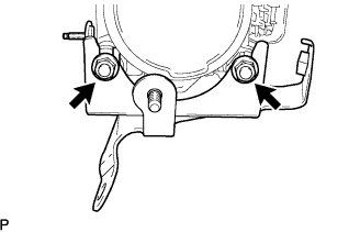
    C102550
  1. Install the brake actuator assembly to the actuator bracket with the 2 nuts.

    Torque:
    5.4 N*m{ 55 kgf*cm , 48 in.*lbf }

    NOTICE:
    1. Do not remove the hole plug until the new actuator assembly is connected because it already contains brake fluid.
    2. Insert the protrusion of the actuator bolt holder between the positioning claws of the actuator bracket No.1.
    3. Insert the positioning pin of the actuator bracket No.1 into the cushion of the actuator assembly.
2. INSTALL BRAKE ACTUATOR COVER


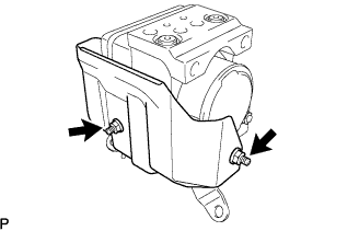
    C102549
  1. Install the actuator cover to the brake actuator assembly with the 2 nuts.

    Torque:
    5.4 N*m{ 55 kgf*cm , 48 in.*lbf }


3. INSTALL BRAKE TUBE


    C102548
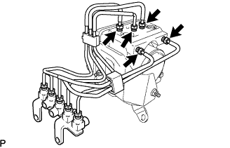
  1. Using SST, install the 5 brake tubes and brake way No.1 to the brake actuator assembly.

    SST
    09023-00101  

    Torque:
    15 N*m{ 155 kgf*cm , 11 ft.*lbf }


4. INSTALL BRAKE ACTUATOR ASSEMBLY WITH FRONT BRAKE TUBE WAY NO.1


    C102547
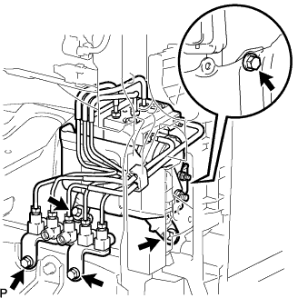
  1. Install the brake actuator assembly with front brake tube way No.1 and the brake tube to the body with the 5 bolts.

    Torque:
    20 N*m{ 204 kgf*cm , 15 ft.*lbf }

    NOTICE:
    Do not bend or damage the brake tube.


    C102546
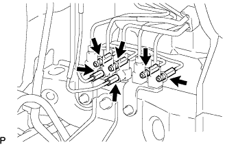
  1. Using SST, connect the 6 brake tubes to the front brake tube way No.1.

    SST
    09023-00101  

    Torque:
    15 N*m{ 155 kgf*cm , 11 ft.*lbf }


    C102544
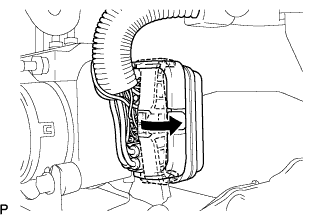
  1. Connect the connector and lock the lock lever.

    NOTICE:
    Check that the lock lever is securely locked.


5. INSTALL FRONT MUDGUARD


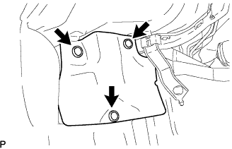
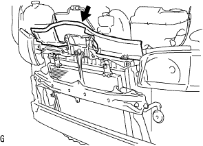
    C102543
  1. Install the front mudguard with the 3 clips.


6. INSTALL SUB RADIATOR ASSEMBLY
  1. For 2KD-FTV
  2. For 5L-E


7. INSTALL HIGH PITCHED HORN ASSEMBLY


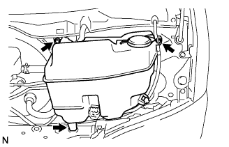
8. INSTALL WINDSHIELD WASHER MOTOR AND PUMP ASSEMBLY
  1. Connect the connector and hose.


    A106861
  1. Install the wind washer jar assembly with the 2 bolts.

    Torque:
    4.9 N*m{ 50 kgf*cm , 43 in.*lbf }


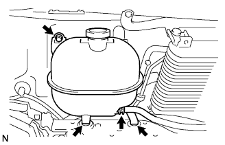
9. INSTALL RADIATOR RESERVE TANK ASSEMBLY
  1. Connect the water by-pass hose No.2 with the clip.

  1. Connect the water by-pass hose No.1 with the clip.


    A106860
  1. Place the reserve tank in the 2 grommets of the radiator upper support, and install the radiator reserve tank assembly with the bolt.

    Torque:
    7.0 N*m{ 71 kgf*cm , 62 in.*lbf }


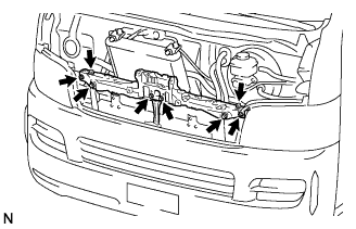
10. INSTALL RADIATOR SUPPORT UPPER


    A106856
  1. Install the radiator upper support with the 6 bolts and 2 screws.

    Torque:
    5.5 N*m{ 56 kgf*cm , 49 in.*lbf }

    HINT:
    If the position of the radiator upper support goes out of alignment while installing it, remove the front bumper and adjust the hood lock brace and bumper stay.


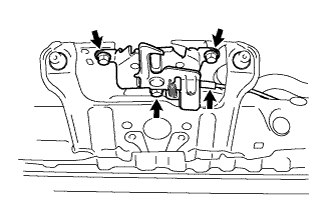
11. INSTALL HOOD LOCK ASSEMBLY
  1. Connect the hood lock cable assembly to the hood lock assembly.


    A114753
  1. Temporarily tighten the hood lock assembly with the 3 bolts from the radiator upper support.


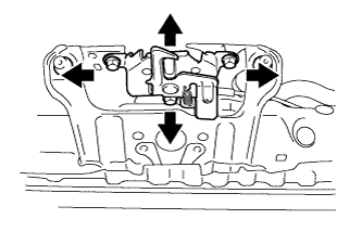
    A114751
  1. Check the hood position and adjust the hood lock assembly position.

  1. Tighten the hood lock assembly with the 3 bolts.

    Torque:
    12 N*m{ 122 kgf*cm , 9 ft.*lbf }


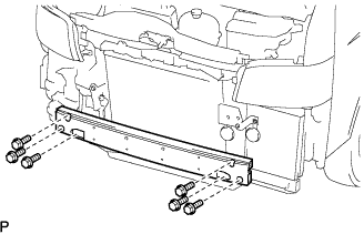
12. INSTALL FRONT BUMPER REINFORCEMENT


    B101617
  1. Install the front bumper reinforcement with the 6 bolts.

    Torque:
    61 N*m{ 622 kgf*cm , 45 ft.*lbf }


13. INSTALL HOOD LOCK SUPPORT BRACE SUB-ASSEMBLY


14. INSTALL AIR INLET DUCT NO.1 (LHD (W/ INTERCOOLER ASSEMBLY))


15. INSTALL AIR INLET DUCT NO.2 (LHD (W/ INTERCOOLER ASSEMBLY))


16. INSTALL RADIATOR SUPPORT SEAL UPPER (LHD (W/O INTERCOOLER ASSEMBLY))


    A116094
  1. Install the air inlet duct No.1 with the 6 clamps.


17. INSTALL FRONT BUMPER


18. INSTALL STEP PLATE COVER RH


19. INSTALL STEP PLATE COVER LH


20. INSTALL RADIATOR GRILLE


21. INSTALL ENGINE UNDER COVER NO.1


22. INSTALL FRONT WHEEL

Torque:
100 N*m{ 1,020 kgf*cm , 74 ft.*lbf }


23. ADD BRAKE FLUID


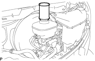
C106088

Fluid:
SAE J1704 or FMVSS No. 116 DOT3 or equivalent


24. BLEED BRAKE LINE
  1. Connect the vinyl tube to the bleeder plug.

  1. Depress the brake pedal several times and loosen the bleeder plug with the pedal held down.

  1. At the point where the fluid stops coming out, tighten the bleeder plug and release the brake pedal.

  1. Repeat this procedure until the air in the brake fluid is completely bled out.

  1. Tighten the bleeder plug.

    1. Front bleeder plug:

      Torque:
      10.8 N*m{ 110 kgf*cm , 8 ft.*lbf }

    2. Rear bleeder plug:

      Torque:
      11.0 N*m{ 112 kgf*cm , 8 ft.*lbf }

  1. Repeat the above procedure to bleed the air out of the brake line for each wheel.


25. INSPECT BRAKE FLUID LEVEL
  1. Check the fluid level and add fluid if necessary.

    Fluid:
    SAE J1704 or FMVSS No.116 DOT3 or equivalent


26. ADD ENGINE COOLANT
  1. For 2TR-FE
  2. For 2KD-FTV
  3. For 5L-E