 |
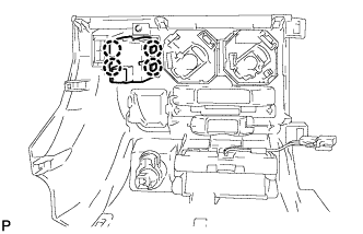
Install the 4 claws and clearance warning indicator.
CLEARANCE WARNING INDICATOR > INSTALLATION |
| 1. INSTALL CLEARANCE WARNING INDICATOR |
|
Install the 4 claws and clearance warning indicator.
| 2. INSTALL AIR CONDITIONER PANEL SUB-ASSEMBLY |
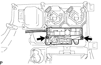 |
Install the heater control base with the 2 screws.
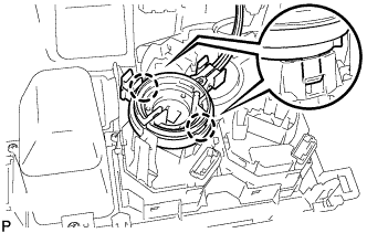 |
Engage the 2 claws to install the defroster damper control cable sub-assembly.
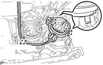 |
Engage the 2 claws to install the boost ventilator control cable sub-assembly.
Install the clamp.
Install the connector.
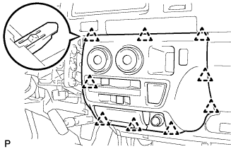 |
Engage the 9 clips to install the air conditioner panel sub-assembly.
| 3. INSTALL INSTRUMENT PANEL FINISH PANEL LOWER CENTER |
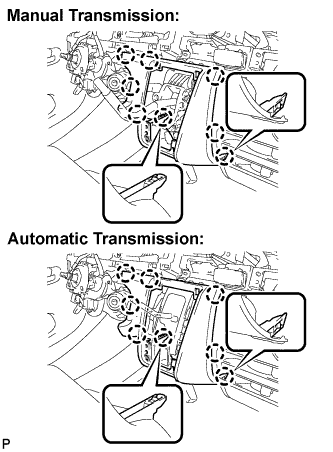 |
Engage the 8 claws and install the instrument panel finish panel lower center.
| 4. INSTALL SHIFTING HOLE COVER ASSEMBLY |
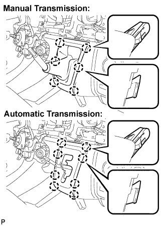 |
Manual Transmission:
Engage the 6 claws and install the shifting hole cover assembly.
Automatic Transmission:
Engage the 8 claws and install the sifting hole cover assembly.
| 5. INSTALL SHIFT LEVER KNOB |
| 6. INSTALL PARKING BRAKE HOLE COVER |
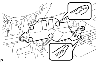 |
Engage the 6 claws and install the parking brake hole cover.
| 7. INSTALL INSTRUMENT PANEL UNDER COVER SUB-ASSEMBLY NO.1 |
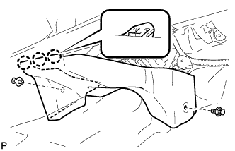 |
Engage the 3 claws.
Install the instrument panel No.1 under cover sub-assembly with the 2 clips.
| 8. INSTALL INSTRUMENT PANEL FINISH PANEL LOWER |
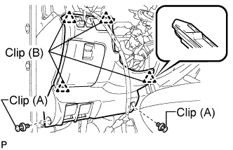 |
Engage the 4 clips (B).
Install the instrument panel finish panel lower with the 2 clips (A).