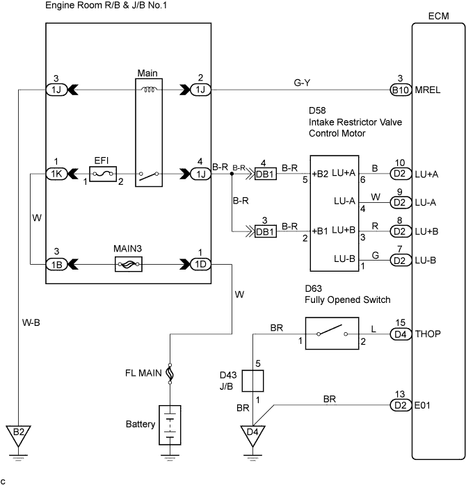
DTC 15 Throttle Motor Circuit Malfunction |
| DTC No. | DTC Detection Condition | Trouble Area |
| 15 | Open or short in intake restrictor valve control motor circuit |
|
| Open or short in fully opened switch circuit |
| 1.INSPECT FULLY OPENED SWITCH |
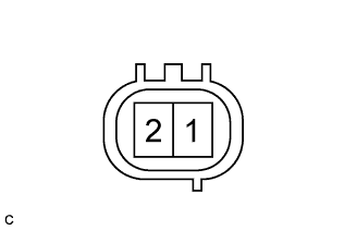 |
Disconnect the fully opened switch connector.
Remove the venturi.
Measure the resistance according to the value(s) in the table below.
| Tester Connection | Specified Condition |
| 1 - 2 (Intake restrictor valve is opened) | Below 1 Ω |
| 1 - 2 (Intake restrictor valve is closed) | 10 kΩ or higher |
|
| ||||
| OK | |
 |
| 2.CHECK HARNESS AND CONNECTOR (FULLY OPENED SWITCH - BODY GROUND, ECM - FULLY OPENED SWITCH) |
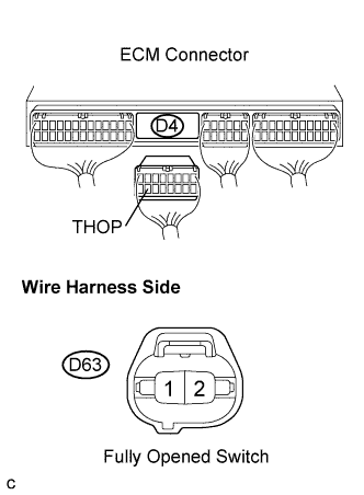 |
Disconnect the fully opened switch connector.
Disconnect the ECM D4 connector.
Measure the resistance according to the value(s) in the table below.
| Tester Connection | Specified Condition |
| (D63-1) - Body ground | Below 1 Ω |
| THOP (D4-15) - (D63-2) | Below 1 Ω |
| Tester Connection | Specified Condition |
| THOP (D4-15) - Body ground | 10 kΩ or higher |
|
| ||||
| OK | |
|
| 3.INSPECT ECM (INTAKE RESTRICTOR VALVE CONTROL MOTOR CIRCUIT) |
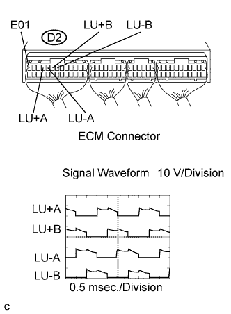 |
During engine racing, measure the waveform according to the value(s) in the table below.
| Tester Connection | Specified Condition |
| LU+A (D2-10) - E01 (D2-13) | Correct waveform shown |
| LU-A (D2-9) - E01 (D2-13) | Correct waveform shown |
| LU+B (D2-8) - E01 (D2-13) | Correct waveform shown |
| LU-B (D2-7) - E01 (D2-13) | Correct waveform shown |
|
| ||||
| OK | ||
 | ||
| ||
| 4.INSPECT INTAKE RESTRICTOR VALVE CONTROL MOTOR |
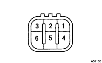 |
Disconnect the intake restrictor valve control motor connector.
Measure the resistance according to the value(s) in the table below.
| Tester Connection | Specified Condition |
| 1 - 2 | 18 to 22 Ω (20°C (68°F)) |
| 2 - 3 | 18 to 22 Ω (20°C (68°F)) |
| 4 - 5 | 18 to 22 Ω (20°C (68°F)) |
| 5 - 6 | 18 to 22 Ω (20°C (68°F)) |
|
| ||||
| OK | |
|
| 5.CHECK HARNESS AND CONNECTOR (INTAKE RESTRICTOR CONTROL MOTOR - ECM) |
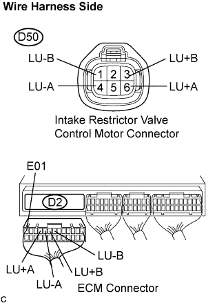 |
Disconnect the intake restrictor valve control motor connector.
Disconnect the ECM D2 connector.
Measure the resistance according to the value(s) in the table below.
| Tester Connection | Specified Condition |
| LU+A (D50-6) - LU+A (D2-10) | Below 1 Ω |
| LU-A (D50-4) - LU-A (D2-9) | Below 1 Ω |
| LU+B (D50-3) - LU+B (D2-8) | Below 1 Ω |
| LU-B (D50-1) - LU-B (D2-7) | Below 1 Ω |
| Tester Connection | Specified Condition |
| LU+A (D2-10) - E01 (D2-13) | 10 kΩ or higher |
| LU-A (D2-9) - E01 (D2-13) | 10 kΩ or higher |
| LU+B (D2-8) - E01 (D2-13) | 10 kΩ or higher |
| LU-B (D2-7) - E01 (D2-13) | 10 kΩ or higher |
|
| ||||
| OK | ||
| ||
| ||

