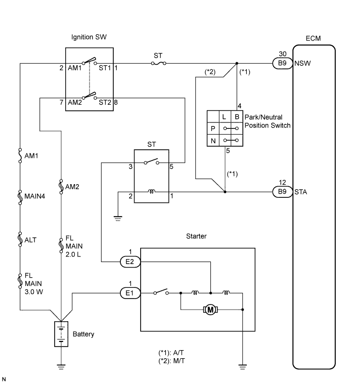
DTC P0617 Starter Relay Circuit High |
| DTC No. | DTC Detection Conditions | Trouble Areas |
| P0617 |
|
|
| 1.READ VALUE OF INTELLIGENT TESTER (STARTER SIGNAL) |
Connect an intelligent tester to the DLC3.
Turn the ignition switch to the ON position and turn the tester ON.
Select the following menu items: Powertrain / Engine and ECT / Data List / Starter Sig.
Check the value displayed on the tester when the ignition switch is turned to the ON and START positions.
| Ignition Switch Positions | ON | START |
| Starter Sig | OFF | ON |
|
| ||||
| NG | |
 |
| 2.INSPECT PARK/NEUTRAL POSITION SWITCH |
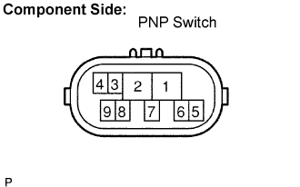 |
Disconnect the P1 PNP switch connector.
Measure the resistance when the transmission gear selector lever is moved to each position.
| Gear Selector Lever Positions | Tester Connections | Specified Conditions |
| P | 2 - 6, 4 - 5 | Below 1 Ω |
| R | 1 - 2 | Below 1 Ω |
| N | 2 - 9, 4 - 5 | Below 1 Ω |
| D | 2 - 7 | Below 1 Ω |
| 2 | 2 - 3 | Below 1 Ω |
| L | 2 - 8 | Below 1 Ω |
Reconnect the PNP switch connector.
|
| ||||
| OK | |
|
| 3.READ VALUE OF INTELLIGENT TESTER (STARTER SIGNAL) |
Connect the intelligent tester to the DLC3.
Turn the ignition switch to the ON position and turn the tester ON.
Select the following menu items: Powertrain / Engine and ECT / Data List / Starter Sig.
Check the value displayed on the tester when the ignition switch is turned to the ON and START positions.
| Ignition Switch Positions | ON | START |
| Starter Sig | OFF | ON |
|
| ||||
| NG | |
|
| 4.INSPECT IGNITION SWITCH |
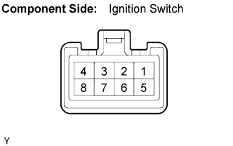 |
Disconnect the H25 ignition switch connector.
Measure the resistance.
| Ignition Switch Positions | Tester Connections | Specified Conditions |
| LOCK | All Terminals | 10 kΩ or higher |
| ACC | 2 - 3 | Below 1 Ω |
| ON | 2 - 3, 2 - 4, 6 - 7 | Below 1 Ω |
| START | 2 - 3, 6 - 7, 1 - 2, 7 - 8 | Below 1 Ω |
Reconnect the ignition switch connector.
|
| ||||
| OK | |
|
| 5.READ VALUE OF INTELLIGENT TESTER |
Connect the intelligent tester to the DLC3.
Turn the ignition switch to the ON position and turn the tester ON.
Select the following menu items: Powertrain / Engine and ECT / Data List / Starter Sig.
Check the value displayed on the tester when the ignition switch is turned to the ON and START positions.
| Ignition Switch Positions | ON | START |
| STARTER SIG | OFF | ON |
|
| ||||
| NG | ||
 | ||
| ||
