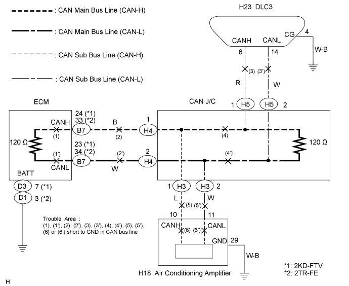
CAN COMMUNICATION SYSTEM > Short to GND in CAN Bus Line |
| Symptom | Trouble Area |
| There is continuity between terminals 4 (CG) and 6 (CANH) or terminals 4 (CG) and 14 (CANL) of the DLC3. |
|
| 1.CHECK CAN BUS LINE SHORT TO GND (DLC3 SUB BUS LINE) |
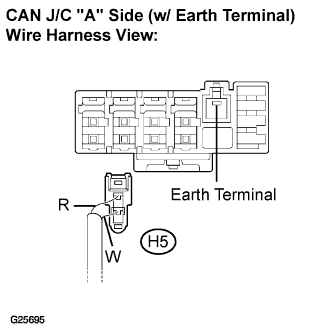 |
Disconnect the DLC3 sub bus line connector (H5) from the CAN J/C.
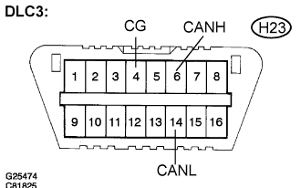 |
Measure the resistance according to the value(s) in the table below.
| Tester connection | Condition | Specified value |
| H23-4 (CG) - H23-6 (CANH) | IG switch OFF | 1 MΩ or higher |
| H23-4 (CG) - H23-14 (CANL) | IG switch OFF | 1 MΩ or higher |
|
| ||||
|
| ||||
| OK | |
 |
| 2.CONNECT CONNECTOR |
Reconnect the DLC3 sub bus line connector (H5) to the CAN J/C.
| NEXT | |
|
| 3.CHECK CAN BUS LINE SHORT TO GND (AIR CONDITIONING AMPLIFIER SUB BUS LINE) |
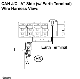 |
Disconnect the air conditioning amplifier sub bus line connector (H3) from the CAN J/C.
|
Measure the resistance according to the value(s) in the table below.
| Tester connection | Condition | Specified value |
| H23-4 (CG) - H23-6 (CANH) | IG switch OFF | 3 kΩ or higher |
| H23-4 (CG) - H23-14 (CANL) | IG switch OFF | 3 kΩ or higher |
|
| ||||
| NG | |
|
| 4.CONNECTOR CONNECT |
Reconnect the air conditioning amplifier sub bus line connector (H3) to the CAN J/C.
| NEXT | |
|
| 5.CHECK CAN BUS LINE SHORT TO GND (ECM MAIN BUS LINE) |
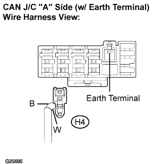 |
Disconnect the ECM main bus line connector (H4) from the CAN J/C.
|
Measure the resistance according to the value(s) in the table below.
| Tester connection | Condition | Specified value |
| H23-4 (CG) - H23-6 (CANH) | IG switch OFF | 3 kΩ or higher |
| H23-4 (CG) - H23-14 (CANL) | IG switch OFF | 3 kΩ or higher |
|
| ||||
| NG | ||
 | ||
| ||
| 6.CHECK CAN BUS LINE SHORT TO GND (AIR CONDITIONING AMPLIFIER SUB BUS LINE) |
Disconnect the air conditioning amplifier connector (H18).
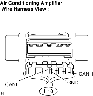 |
Measure the resistance according to the value(s) in the table below.
| Tester connection | Condition | Specified value |
| H18-10 (CANH) - H18-29 (GND) | IG switch OFF | 1 MΩ or higher |
| H18-11 (CANL) - H18-29 (GND) | IG switch OFF | 1 MΩ or higher |
|
| ||||
|
| ||||
| OK | ||
| ||
| ||
| 7.CHECK CAN BUS LINE SHORT TO GND (ECM MAIN BUS LINE) |
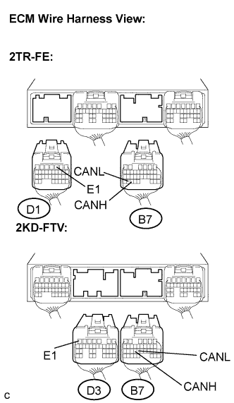 |
Disconnect the ECM connectors (B7) and (D1). (2TR-FE)
Disconnect the ECM connector (B7) and (D3). (2KD-FTV)
Measure the resistance according to the value(s) in the table below.
| Tester Connection | Condition | Specified value |
| B7-33 (CANH) - D1-3 (E1) | IG switch OFF | 1 MΩ or higher |
| B7-34 (CANL) - D1-3 (E1) | IG switch OFF | 1 MΩ or higher |
| Tester Connection | Condition | Specified value |
| B7-24 (CANH) - D3-7 (E1) | IG switch OFF | 1 MΩ or higher |
| B7-23 (CANL) - D3-7 (E1) | IG switch OFF | 1 MΩ or higher |
|
| ||||
|
| ||||
| OK | ||
| ||
| ||

