 |
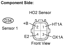
Disconnect the D34 Heated Oxygen (HO2) sensor connector.
DTC P0135 Oxygen (A/F) Sensor Heater Circuit (Bank 1 Sensor 1) |
| DTC No. | DTC Detecting Condition | Trouble Area |
| P0135 | When heater operates, heater current exceeds 2 A (2 trip detection logic) |
|
| Heater current of 0.2 A or less when heater operates (2 trip detection logic) |
| 1.INSPECT HEATED OXYGEN SENSOR |
|
Disconnect the D34 Heated Oxygen (HO2) sensor connector.
Measure the resistance between the terminals of the HO2 sensor connector.
| Tester Connections | Specified Conditions |
| HT1A (1) - +B (2) | 11 to 16 Ω at 20°C (68°F) |
| HT1A (1) - E2 (4) | 10 kΩ or higher |
Reconnect the HO2 sensor connector.
|
| ||||
| OK | |
 |
| 2.INSPECT ECM (HT1B VOLTAGE) |
 |
Turn the ignition switch to the ON position.
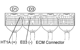
Measure the voltage between the terminals of the ECM connectors.
| Tester Connections | Specified Conditions |
| HT1A (D1-1) - E03 (D3-4) | 9 to 14 V |
|
| ||||
| OK | |
|
| 3.CHECK HARNESS AND CONNECTOR (HO2 SENSOR - ECM, HO2 - INTEGRATION RELAY) |
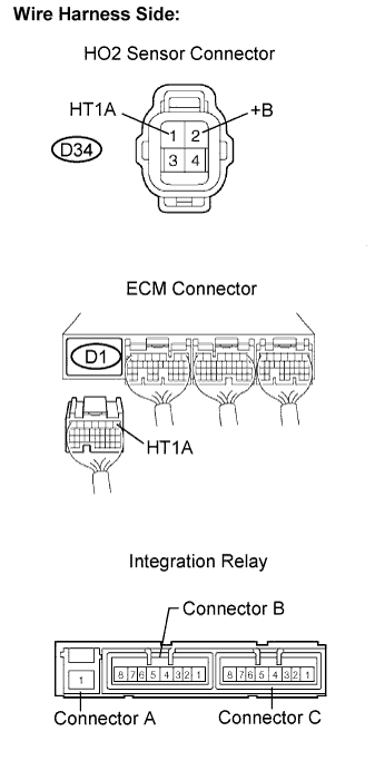 |
Check the harness and connectors between the ECM and HO2 sensor.
Disconnect the D34 or HO2 sensor connector.
Disconnect the D1 ECM connector.
Measure the resistance.
| Tester Connections | Specified Conditions |
| HT1A (D34-1) - HT1A (D1-1) | Below 1 Ω |
| Tester Connections | Specified Conditions |
| HT1A (D34-1) or HT1A (D1-1) - Body ground | 10 kΩ or higher |
Reconnect the HO2 sensor connector.
Reconnect the ECM connector.
Check the harness and connector between the HO2 sensor and integration relay (MAIN relay).
Disconnect the D35 HO2 sensor connector.
Remove the integration relay from the engine room No.1.
Measure the resistance.
| Tester Connections | Specified Conditions |
| +B (D34-2) - Integration relay (B4) | Below 1 Ω |
| Tester Connections | Specified conditions |
| +B (D34-2) or Integration relay (B4) - Body ground | 10 kΩ or higher |
Reconnect the HO2 sensor connector.
Reinstall the integration relay (MAIN relay).
|
| ||||
| OK | |
|
| 4.INSPECT ECM POWER SOURCE CIRCUIT |
|
| ||||
| OK | ||
 | ||
| ||

