Home › STEERING › POWER STEERING › POWER STEERING GEAR

POWER STEERING GEAR > INSTALLATION

for Preparation Click here


1. INSTALL POWER STEERING LINK ASSEMBLY


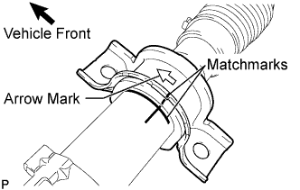
    C106154E01
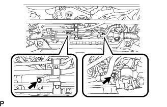
  1. Align the matchmarks on the steering rack housing bracket No.2, steering rack housing grommet No.2, and the power steering link assembly.

    HINT:
    Make sure that the arrow mark on the steering rack housing bracket No.2 faces toward the front of the vehicle.
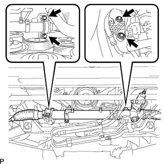
    C106155
  1. Install the power steering link assembly with the 4 bolts.

    Torque:
    123 N*m{ 1254 kgf*cm , 91 ft.*lbf }


2. CONNECT PRESSURE FEED TUBE ASSEMBLY


    C106148
  1. Install the pressure feed tube clamp to the power steering link assembly with the 2 bolts.

    Torque:
    12 N*m{ 117 kgf*cm , 9 ft.*lbf }


    C106153E01
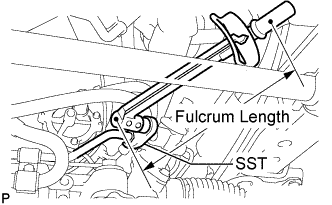
  1. Using SST, connect the pressure feed tube assembly (pressure tube side) to the power steering link assembly.

    SST
    09023-12701  

    Torque:
    41 N*m{ 413 kgf*cm , 30 ft.*lbf }

    NOTICE:
    Use a torque wrench with a fulcrum length of 345 mm (13.58 in.).


    C106151E01
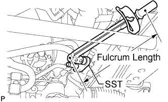
  1. Using SST, install the steering gear outlet return tube to the power steering link assembly.

    SST
    09023-12701  

    Torque:
    41 N*m{ 413 kgf*cm , 30 ft.*lbf }

    NOTICE:
    Use a torque wrench with a fulcrum length of 345 mm (13.58 in.).

  1. Connect the pressure feed tube assembly (return tube side) to the steering gear outlet return tube with the clip.


3. CONNECT TIE ROD END SUB-ASSEMBLY LH
  1. Connect the tie rod end sub-assembly LH to the steering knuckle with the nut.

    Torque:
    50 N*m{ 510 kgf*cm , 37 ft.*lbf }

  1. Install a new cotter pin.

    NOTICE:
    Further tighten the nut up to 60° if the holes for the cotter pin are not aligned.


4. CONNECT TIE ROD END SUB-ASSEMBLY RH

HINT:
Perform the same procedure as for the LH side.


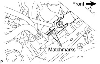
5. CONNECT STEERING TORQUE SHAFT ASSEMBLY


    C106143E01
  1. Align the matchmarks on the steering torque shaft assembly and the power steering link assembly.


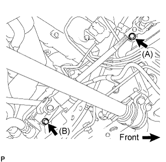
    C106142E01
  1. Install bolt (B) and tighten the 2 bolts.

    Torque:
    35 N*m{ 360 kgf*cm , 26 ft.*lbf }


6. ADD POWER STEERING FLUID


7. BLEED POWER STEERING FLUID


8. CHECK FOR POWER STEERING FLUID LEAKS


9. INSTALL FRONT WHEELS

Torque:
103 N*m{ 1,050 kgf*cm , 76 ft.*lbf }


10. PLACE FRONT WHEELS FACING STRAIGHT AHEAD


11. INSTALL ENGINE UNDER COVER NO.1


12. INSPECT AND ADJUST FRONT WHEEL ALIGNMENT
(Click here)