 |
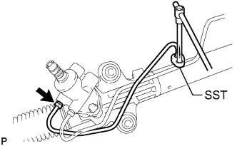
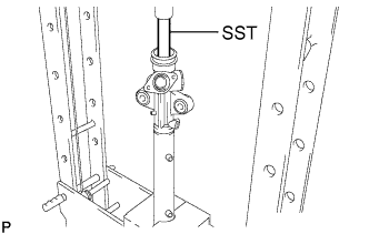
Using SST, remove the steering left turn pressure tube.
- SST
- 09023-38201
POWER STEERING GEAR > DISASSEMBLY |
| 1. REMOVE STEERING LEFT TURN PRESSURE TUBE |
|
Using SST, remove the steering left turn pressure tube.
| 2. REMOVE STEERING RIGHT TURN PRESSURE TUBE |
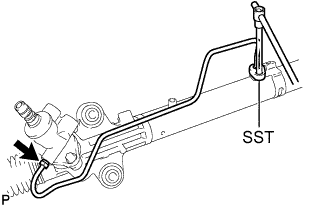 |
Using SST, remove the steering right turn pressure tube.
| 3. FIX POWER STEERING LINK ASSEMBLY |
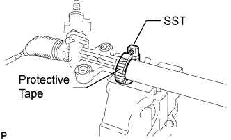 |
Using SST, secure the power steering link assembly.
| 4. REMOVE TIE ROD END SUB-ASSEMBLY LH |
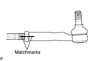 |
Put matchmarks on the tie rod end sub-assembly LH and the steering rack end sub-assembly.
Loosen the lock nut, and remove the tie rod end sub-assembly LH and the lock nut.
| 5. REMOVE TIE ROD END SUB-ASSEMBLY RH |
| 6. REMOVE STEERING RACK BOOT CLIP |
Using pliers, remove the 2 steering rack boot clips.
| 7. REMOVE STEERING RACK BOOT NO.2 CLAMP |
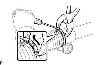 |
Using pliers and a screwdriver, remove the steering rack boot No.2 clamp as shown in the illustration.
| 8. REMOVE STEERING RACK BOOT NO.1 CLAMP |
| 9. REMOVE STEERING RACK BOOT NO.2 |
| 10. REMOVE STEERING RACK BOOT NO.1 |
| 11. REMOVE STEERING RACK END SUB-ASSEMBLY |
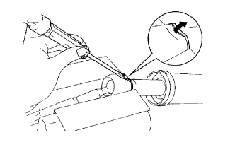 |
Using a screwdriver and a hammer, unstake the RH and LH claw washers.
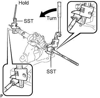 |
Using SST, remove the steering rack end sub-assembly (LH side) and the claw washer.
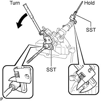 |
Using SST, remove the steering rack end sub-assembly (RH side) and the claw washer.
| 12. REMOVE POWER STEERING RACK GUIDE |
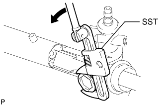 |
Using SST, remove the power steering rack guide spring cap nut.
Using a straight hexagon wrench 24 mm (0.94 in.), remove the power steering rack guide spring cap.
Remove the compression spring and the power steering rack guide.
Remove the rack guide seat from the power steering rack guide.
| 13. REMOVE POWER STEERING CONTROL VALVE |
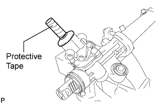
Wrap the serration of the power steering control valve with protective tape.
 |
Remove the dust cover.
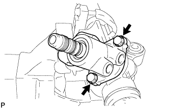 |
Remove the 2 bolts and the control valve housing with the control valve.
Remove the gasket.
Wrap protective tape around the spline of the power steering control valve in order to prevent damaging oil seal.
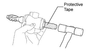 |
Using a plastic hammer, remove the power steering control valve.
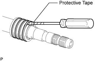 |
Using a screwdriver, remove the 4 control valve spacers.
| 14. REMOVE POWER STEERING CONTROL VALVE LOWER OIL SEAL |
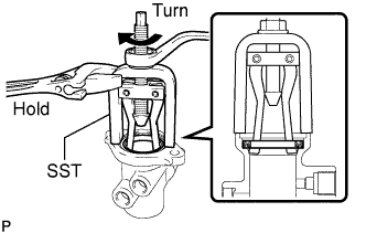 |
Using SST, remove the power steering control valve lower oil seal.
| 15. REMOVE POWER STEERING CONTROL VALVE UPPER OIL SEAL |
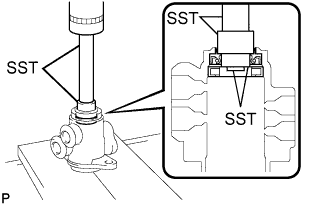 |
Using SST and a press, remove the power steering control valve upper oil seal and the power steering upper bearing from the control valve housing.
| 16. REMOVE CYLINDER END STOPPER |
Body type narrow:
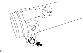 |
Loosen the bolt.
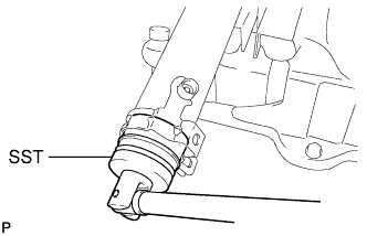 |
Using SST, remove the cylinder end stopper from the rack housing.
Remove the tube support retainer.
Body type wide:
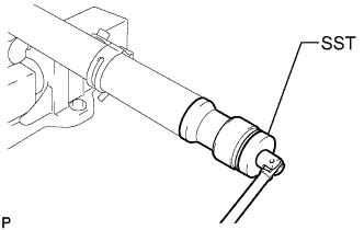 |
Using SST, remove the cylinder end stopper and the spacer from the rack housing.
Using a screwdriver, remove the O-ring from the cylinder end stopper.
Using a screwdriver, remove the bushing from the cylinder end stopper.
| 17. REMOVE POWER STEERING RACK |
Temporarily install the service bolt to the power steering rack.
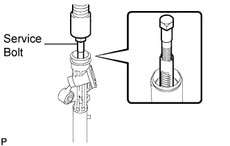 |
Using a press, remove the power steering rack.
Remove the cylinder end stopper oil seal from the power steering rack.
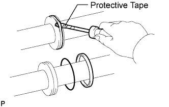 |
Using a screwdriver, remove the oil seal and the O-ring from the power steering rack.
| 18. REMOVE POWER STEERING CYLINDER TUBE OIL SEAL |
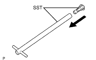 |
Install SST (09612-07120) to SST (09612-07210).
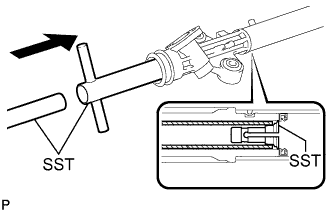 |
Insert SST (09612-07210) into the rack housing at a slant until it comes in contact with the power steering cylinder tube oil seal. Install SST (09612-07220) to SST (09612-07210).
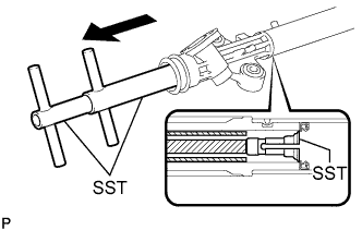 |
Hold SST, (09612-70220) and pull SST (09612-07210) to position SST (09612-07120) to the inside of the rack housing.
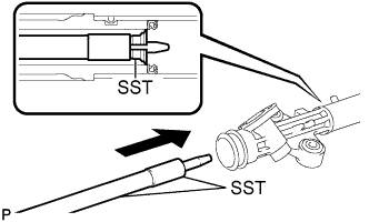 |
Install SST (09612-07240) to SST (09612-07230). Insert the tip of SST (09612-07230) into the service hole of SST (09612-07120) in the rack housing.
 |
Install SST (09951-07150) to SST (09612-07230). Using a press, remove the power steering cylinder tube oil seal.