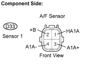
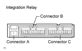
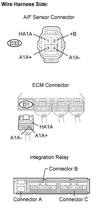
DTC No.
| DTC Detecting Condition
| Trouble Area
|
P2238
| A/F sensor circuit low
| - Open in A/F sensor circuit
|
- Condition (a) continues for 5.0 sec. or more:
- AF+ less than 0.5 V
| - Open or short in A/F sensor circuit
- A/F sensor
- A/F sensor heater
- Integration relay (A/F HEATER RELAY)
- A/F sensor heater and relay circuit
- ECM
|
- Condition (a) continues for 5.0 sec. or more:
- (AF+) - (AF-) less than 0.1 V
|
P2239
| A/F sensor circuit high
| - Short in A/F sensor circuit
|
- Condition (a) continues for 5.0 sec. or more:
- AF+ greater than 4.5 V
| - Open or short in A/F sensor circuit
- A/F sensor
- A/F sensor heater
- Integration relay (A/F HEATER RELAY)
- A/F sensor heater and relay circuit
- ECM
|
- Condition (a) continues for 5.0 sec. or more:
- (AF+) - (AF-) greater than 0.8 V
|
P2252
| - Condition (a) continues for 5.0 sec. or more:
- AF- less than 0.5 V
| - Open or short in A/F sensor circuit
- A/F sensor
- A/F sensor heater
- Integration relay (A/F HEATER RELAY)
- A/F sensor heater and relay circuit
- ECM
|
P2253
| - Condition (a) continues for 5.0 sec. or more:
- AF- greater than 4.5 V
|
Case
| A/F Sensor (Sensor 1)
Output Voltage
| HO2 Sensor (Sensor 2)
Output Voltage
| Mainly Suspected Trouble Areas
|
1
| Injection volume
+25 %
-12.5 %
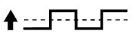
| 
| Injection volume
+25 %
-12.5 %
|
| -
|
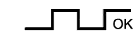
Output voltage
More than 3.35 V
Less than 3.0 V
| 
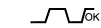
| Output voltage
More than 0.5 V
Less than 0.4 V
| 
|
2
| Injection volume
+25 %
-12.5 %
|
| Injection volume
+25 %
-12.5 %
|
| - A/F sensor
- A/F sensor heater
- A/F sensor circuit
|
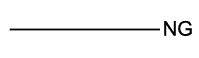
Output voltage
Almost no reaction
| 
| Output voltage
More than 0.5 V
Less than 0.4 V
|
|
3
| Injection volume
+25 %
-12.5 %
|
| Injection volume
+25 %
-12.5 %
|
| - HO2 sensor
- HO2 sensor heater
- HO2 sensor circuit
|
Output voltage
More than 3.35 V
Less than 3.0 V
|
| Output voltage
Almost no reaction
|
|
4
| Injection volume
+25 %
-12.5 %
|
| Injection volume
+25 %
-12.5 %
|
| - Injector
- Fuel pressure
- Gas leakage from exhaust system
(Air-fuel ratio extremely lean or rich)
|
Output voltage
Almost no reaction
|
| Output voltage
Almost no reaction
|
|