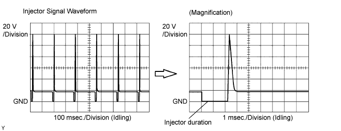
SFI SYSTEM (w/o Secondary Air Injection System) > Injector Circuit |
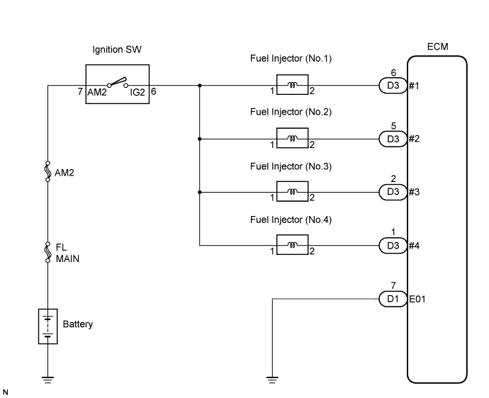
| 1.INSPECT ECM (#1, #2, #3 or #4 VOLTAGE) |
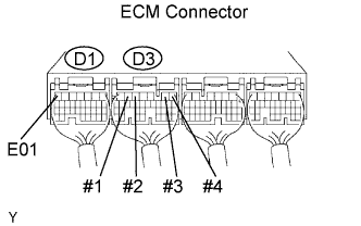 |
Turn the ignition switch to the ON position.
Measure the voltage between the terminals of the ECM connector.
| Tester Connections | Specified Conditions |
| #1 (D3-6) - E01 (D1-7) | 9 to 14 V |
| #2 (D3-5) - E01 (D1-7) | 9 to 14 V |
| #3 (D3-2) - E01 (D1-7) | 9 to 14 V |
| #4 (D3-1) - E01 (D1-7) | 9 to 14 V |
|
| ||||
| NG | |
 |
| 2.INSPECT FUEL INJECTOR ASSEMBLY |
|
| ||||
| OK | |
|
| 3.CHECK HARNESS OR CONNECTOR (INJECTOR - ECM, INJECTOR - IGNITION SWITCH) |
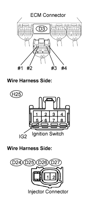 |
Check the harness and connectors between the injector and ECM.
Disconnect the injector connector(s).
Disconnect the D3 ECM connector.
Measure the resistance according to the value(s) in the table below.
| Tester Connection | Specified Condition |
| Injector (D24-2) - #1 (D3-6) | Below 1 Ω |
| Injector (D25-2) - #2 (D3-5) | Below 1 Ω |
| Injector (D26-2) - #3 (D3-2) | Below 1 Ω |
| Injector (D27-2) - #4 (D3-1) | Below 1 Ω |
| Tester Connection | Specified Condition |
| Injector (D24-2) or #1 (D3-6) - Body ground | 10 kΩ or higher |
| Injector (D25-2) or #2 (D3-5) - Body ground | 10 kΩ or higher |
| Injector (D26-2) or #3 (D3-2) - Body ground | 10 kΩ or higher |
| Injector (D27-2) or #4 (D3-1) - Body ground | 10 kΩ or higher |
Reconnect the injector connector(s).
Reconnect the ECM connector.
Check the harness and connectors between the injector and ignition switch.
Disconnect the injector connector(s).
Disconnect the H25 ignition switch connector.
Measure the resistance according to the value(s) in the table below.
| Tester Connection | Specified Condition |
| Injector (D24-1) - IG2 (H25-6) | Below 1 Ω |
| Injector (D25-1) - IG2 (H25-6) | Below 1 Ω |
| Injector (D26-1) - IG2 (H25-6) | Below 1 Ω |
| Injector (D27-1) - IG2 (H25-6) | Below 1 Ω |
| Tester Connection | Specified Condition |
| Injector (D24-1) or IG2 (H25-6) - Body ground | 10 kΩ or higher |
| Injector (D25-1) or IG2 (H25-6) - Body ground | 10 kΩ or higher |
| Injector (D26-1) or IG2 (H25-6) - Body ground | 10 kΩ or higher |
| Injector (D27-1) or IG2 (H25-6) - Body ground | 10 kΩ or higher |
Reconnect the injector connector.
Reconnect the ignition switch connector.
|
| ||||
| OK | ||
 | ||
| ||
| 4.CHECK HARNESS OR CONNECTOR (ECM GROUND) |
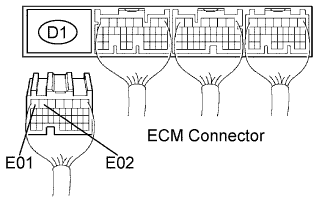 |
Disconnect the D1 ECM Connector.
Measure the resistance according to the value(s) in the table below.
| Tester Connection | Specified Condition |
| E01 (D1-7) - Body ground | Below 1 Ω |
| E02 (D1-6) - Body ground | Below 1 Ω |
Reconnect the ECM connector.
|
| ||||
| OK | |
|
| 5.INSPECT FUEL INJECTOR ASSEMBLY |
|
| ||||
| OK | ||
| ||
| ||

