 |
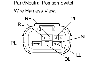
Disconnect the connector from the park/neutral position switch.
METER / GAUGE SYSTEM > ON-VEHICLE INSPECTION |
| 1. INSPECT SPEEDOMETER |
Using a speedometer tester, check the speedometer indication according to the table below.
| Standard Indication | Allowable Range |
| 20 | 21.0 to 23.5 |
| 40 | 42.0 to 44.5 |
| 60 | 62.0 to 66.0 |
| 80 | 83.1 to 87.1 |
| 100 | 103.9 to 108.4 |
| Standard Indication | Allowable Range Datain ( ) is for reference |
| 20 | (21.0 to 25.0) |
| 40 | 41.7 to 46.2 |
| 60 | 62.7 to 67.2 |
| 80 | 83.4 to 88.4 |
| 100 | 104.3 to 1.9.3 |
| 120 | 125.1 to 130.6 |
| 140 | 145.8 to 151.8 |
| 160 | 166.2 to 173.2 |
Check the deviation from the acceptable value of the speedometer indication.
| 2. INSPECT TACHOMETER |
Connect a tune-up test tachometer, and start the engine.
Compare the test results and the tachometer indications.
| Standard Indication (rpm) | Allowable Range (rpm) Data in ( ) are for reference |
| 700 | 630 to 700 |
| 1,000 | (900 to 1,100) |
| 2,000 | (1,850 to 2,150) |
| 3,000 | 2,800 to 3,200 |
| 4,000 | (3,800 to 4,200) |
| 5,000 | 4,800 to 5,200 |
| 6,000 | (5,750 to 6,250) |
| 3. INSPECT LOW OIL PRESSURE WARNING LIGHT |
Inspect the circuit.
Disconnect the connector from the low oil pressure switch.
Turn the ignition switch ON.
Connect the terminal of the wire harness side connector and ground, then check the low oil pressure warning light.
| 4. INSPECT ENGINE OIL LEVEL WARNING LIGHT |
Gasoline engine
Disconnect the connector from the engine oil level sensor.
Turn the ignition switch ON.
Diesel engine
Turn the ignition switch ON.
Wait until the engine coolant temperature goes over 80°C (176°F)
Turn the ignition switch off.
Disconnect the connector from the engine oil level sensor.
Turn the ignition switch ON.
| 5. INSPECT SEDIMENTER/FILTER WARNING LIGHT |
Disconnect the connector from the fuel sedimenter warning switch.
Turn the ignition switch ON.
Ground the terminal of the wire harness side connector, then check the sedimenter/filter warning light.
| 6. INSPECT A/T SHIFT POSITION INDICATOR LIGHT |
|
Disconnect the connector from the park/neutral position switch.
Turn the ignition switch ON.
Ground the terminal of the wire harness side connector, then check the A/T shift position indicator light.
| Tester Connection | A/T Shift Position Indicator Light |
| RB (D37-2) - PL (D37-6) | P |
| RB (D37-2) - RL (D37-1) | R |
| RB (D37-2) - NL (D37-9) | N |
| RB (D37-2) - DL (D37-7) | D |
| RB (D37-2) - 2L (D37-3) | 2 |
| RB (D37-2) - LL (D37-8) | L |