Disconnect the 5E, 5G, and 5M instrument J/B connectors.
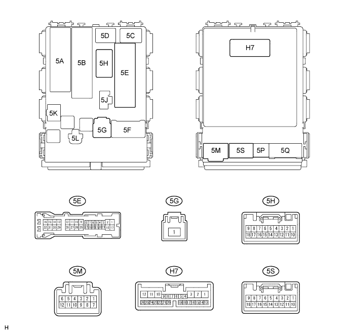
Measure the voltage and resistance between the wire harness side connectors and body ground.
- Voltage:
Symbols (Terminal No.) Wiring Color Terminal Description Condition Specified Condition +B (5G-1) - Body ground B-G - Body ground Battery power supply Always 10 to 14 V ECUB (5E-17) - Body ground W-R - Body ground Battery power supply Always 10 to 14 V
- Resistance:
Symbols (Terminal No.) Wiring Color Terminal Description Condition Specified Condition GND (5E-12) - Body ground W-B - Body ground Ground Always Below 1 Ω GND (5M-7) - Body ground W-B - Body ground Ground Always Below 1 Ω
Reconnect the 5E, 5G, and 5M instrument J/B connectors.
Measure the resistance and voltage according to the value(s) in the table below.
- Resistance:
Symbols (Terminal No.) Wiring Color Terminal Description Condition Specified Condition CLTE (H7-24) - GND (5E-12) W - W-B Ground Always Below 1 Ω
- Voltage:
Symbols (Terminal No.) Wiring Color Terminal Description Condition Specified Condition DCTY (5E-27) - GND (5E-12) R-G - W-B (*1)
R-L - W-B (*2)Driver side door courtesy switch signal Driver side door open Below 1 V DCTY (5E-27) - GND (5E-12) R-G - W-B (*1)
R-L - W-B (*2)Driver side door courtesy switch signal Driver side door closed 10 to 14 V TRLY (5H-3) - GND (5E-12) R - W-B Headlight control switch signal Headlight control switch OFF 10 to 14 V TRLY (5H-3) - GND (5E-12) R - W-B Headlight control switch signal Headlight control switch AUTO Below 1 V AUTO (H7-10) - GND (5E-12) O - W-B Headlight control switch signal Headlight control switch OFF 10 to 14 V AUTO (H7-10) - GND (5E-12) O - W-B Headlight control switch signal Headlight control switch AUTO Below 1 V HRLY (H7-14) - GND (5E-12) R-Y - W-B Headlight control switch signal Headlight control switch OFF 10 to 14 V HRLY (H7-14) - GND (5E-12) R-Y - W-B Headlight control switch signal Headlight control switch AUTO Below 1 V CLTS (H7-25) - GND (5E-12) B - W-B Automatic light control sensor signal Ignition switch OFF Below 1 V CLTS (H7-25) - GND (5E-12) B - W-B Automatic light control sensor signal Ignition switch ON
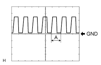
Headlight control switch AUTOSignal waveform
(see waveform 1)CLTB (H7-26) - GND (5E-12) P - W-B Automatic light control sensor signal Always 10 to 14 V EHW (5S-17) - GND (5E-12) G-W - W-B Hazard warning switch signal Hazard warning switch OFF 10 to 14 V EHW (5S-17) - GND (5E-12) G-W - W-B Hazard warning switch signal Hazard warning switch ON Below 1 V
*1: LHD
*2: RHD
Waveform 1
Item Description Terminal CLTS - CLTE Gauge 5 V/DIV, 5 ms/DIV Condition Ignition switch ON, Headlight dimmer SW in AUTO - HINT:
- If the ambient light becomes brighter, width A becomes narrower.
 |