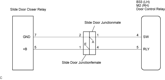
SLIDE DOOR CLOSER SYSTEM > Slide Door Closer Relay Power Source Circuit |
| 1.CHECK WIRE HARNESS (SLIDE DOOR CLOSER RELAY - BATTERY AND BODY GROUND) |
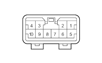 |
Disconnect the slide door closer relay connector.
Measure the resistance according to the value(s) in the table below.
| Tester Connection | Condition | Specified Condition |
| 7 (GND) - Body ground | Always | Below 1 Ω |
Measure the voltage according to the value(s) in the table below.
| Tester Connection | Condition | Specified Condition |
| 5 (+B) - Body ground | Slide door OPEN → Halfway position | 0 V → 10 to 14 V |
|
| ||||
| OK | ||
 | ||
| ||
| 2.INSPECT SLIDE DOOR CONTROL JUNCTIONFEMALE |
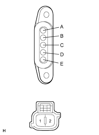 |
Inspect the slide door control junctionfemale.
Measure the resistance according to the value(s) in the table below.
| Tester Connection | Condition | Specified Condition |
| A - 1 | Always | Below 1 Ω |
| E - 2 | Always | Below 1 Ω |
|
| ||||
| OK | |
 |
| 3.INSPECT SLIDE DOOR CONTROL JUNCTIONMALE |
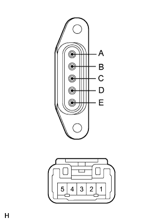 |
Inspect the slide door control junctionmale.
Measure the resistance according to the value(s) in the table below.
| Tester Connection | Condition | Specified Condition |
| A - 1 | Always | Below 1 Ω |
| E - 4 | Always | Below 1 Ω |
|
| ||||
| OK | |
|
| 4.CHECK WIRE HARNESS (SLIDE DOOR CLOSER RELAY - DOOR CONTROL RELAY) |
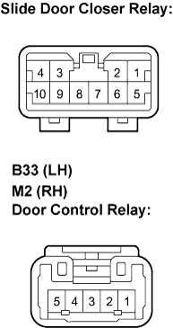 |
Disconnect the B33 (M2) and slide door lock assembly connectors.
Measure the resistance according to the value(s) in the table below.
| Tester Connection | Condition | Specified Condition |
| B33-4 - 7 | Always | Below 1 Ω |
| B33-5 - 5 | Always | 10 kΩ or higher |
| Tester Connection | Condition | Specified Condition |
| M2-4 - 7 | Always | Below 1 Ω |
| M2-5 - 5 | Always | 10 kΩ or higher |
|
| ||||
| OK | ||
| ||
| ||

