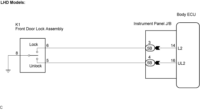
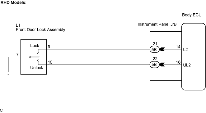
POWER DOOR LOCK CONTROL SYSTEM > Front Passenger Side Door Key Lock and Unlock Switch Circuit |
| 1.INSPECT FRONT DOOR LOCK ASSEMBLY (DOOR KEY LOCK AND UNLOCK SWITCH) |
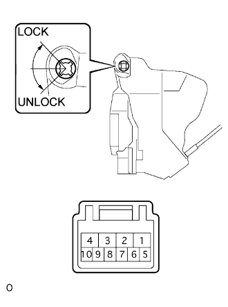 |
LHD Models:
Inspect the front door lock assembly.
Measure the resistance when the switch is operated according to the value(s) in the table below.
| Tester Connection | Door Lock Condition | Specified Condition |
| 5 - 8 | ON (Door lock set to UNLOCK) | Below 1 Ω |
| 6 - 8 | OFF (Door lock set to LOCK) | Below 1 Ω |
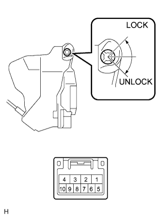 |
RHD Models:
Inspect the front door lock assembly.
Measure the resistance when the switch is operated according to the value(s) in the table below.
| Tester Connection | Door Lock Condition | Specified Condition |
| 10 - 7 | ON (Door lock set to UNLOCK) | Below 1 Ω |
| 9 - 7 | OFF (Door lock set to LOCK) | Below 1 Ω |
|
| ||||
| OK | |
 |
| 2.CHECK WIRE HARNESS (FRONT DOOR LOCK ASSEMBLY - INSTRUMENT PANEL J/B) |
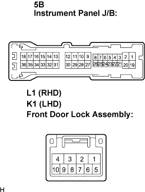 |
Disconnect the K1 (L1) connector.
Disconnect the instrument panel J/B connector.
Measure the resistance according to the value(s) in the table below.
| Tester Connection | Door Lock Condition | Specified Condition |
| 5B-3 - K1-6 | Always | Below 1 Ω |
| 5B-4 - K1-5 | Always | Below 1 Ω |
| K1-8 - Body ground | Always | Below 1 Ω |
| Tester Connection | Door Lock Condition | Specified Condition |
| 5B-21 - L1-9 | Always | Below 1 Ω |
| 5B-22 - L1-10 | Always | Below 1 Ω |
| L1-7 - Body ground | Always | Below 1 Ω |
|
| ||||
| OK | ||
 | ||
| ||
