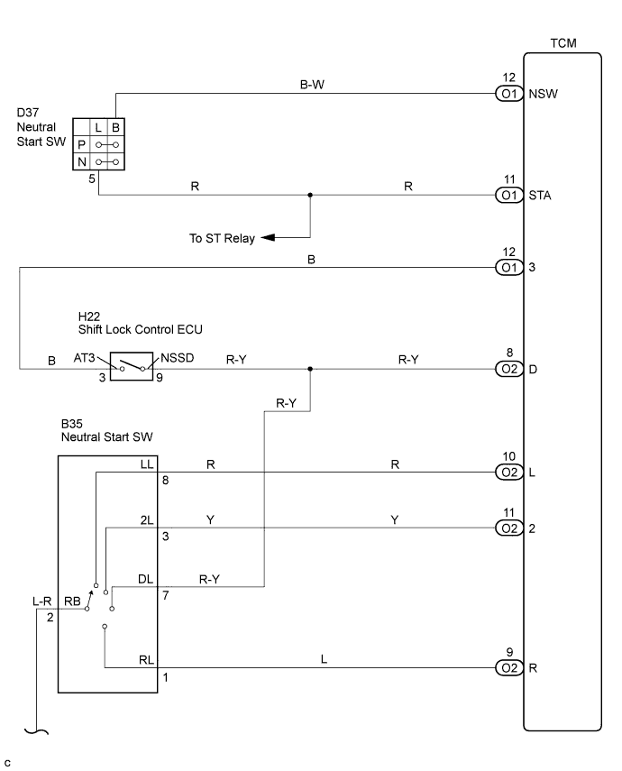
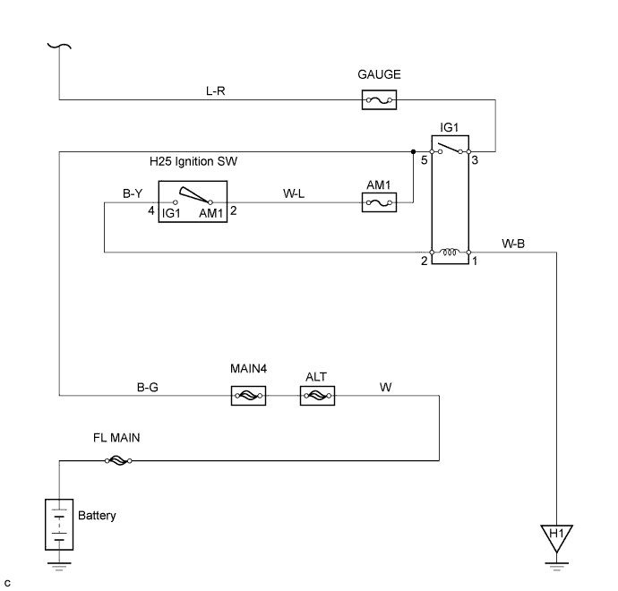
ELECTRONIC CONTROLLED AUTOMATIC TRANSMISSION SYSTEM > Park / Neutral Position Switch Circuit |
| DATA LIST |
Warm up the engine.
Turn the ignition switch off.
Connect the Intelligent Tester to the DLC3.
Turn the ignition switch to the ON position.
Turn on the tester.
Select the item "Enter / Power train / ECT / Data List".
Follow the instructions on the tester and read the Data List.
| Item | Measurement Item/ Range (display) | Normal Condition | Diagnostic Note |
| Neutral Position SW Signal | PNP SW Status/ ON or OFF | Shift lever position is; P and N: ON Except P and N: OFF | When the shift lever position displayed on the Intelligent tester differs from the actual position, adjustment of the PNP switch or the shift cable may be incorrect. |
| Shift SW Status (L Range) | PNP SW Status/ ON or OFF | Shift lever position is; L: ON Except L: OFF | ↑ |
| Shift SW Status (2 Range) | PNP SW Status/ ON or OFF | Shift lever position is; 2 and L: ON Except 2 and L: OFF | ↑ |
| Shift SW Status (3 Range) | PNP SW Status/ ON or OFF | Shift lever position is; 3: ON Except 3: OFF | ↑ |
| Shift SW Status (R Range) | PNP SW Status/ ON or OFF | Shift lever position is; R: ON Except R: OFF | ↑ |
| Shift SW Status (D Range) | PNP SW Status/ ON or OFF | Shift lever position is; D and 3: ON Except D and 3: OFF | ↑ |
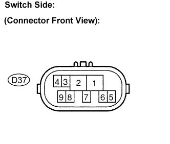
| 1.INSPECT PARK/NEUTRAL POSITION SWITCH ASSEMBLY |
 |
Jack up the vehicle.
Disconnect the park/neutral position switch connector.
Measure the resistance according to the value(s) in the table below when the shift lever is moved to each position.
| Shift Position | Tester Connection | Specified Condition |
| P | 2 - 6 and 4 - 5 | Below 1 Ω |
| Except P | ↑ | 10 kΩ or higher |
| R | 2 - 1 | Below 1 Ω |
| Except R | ↑ | 10 kΩ or higher |
| N | 2 - 9 and 4 - 5 | Below 1 Ω |
| Except N | ↑ | 10 kΩ or higher |
| D and 3 | 2 - 7 | Below 1 Ω |
| Except D and 3 | ↑ | 10 kΩ or higher |
| 2 | 2 - 3 | Below 1 Ω |
| Except 2 | ↑ | 10 kΩ or higher |
| L | 2 - 8 | Below 1 Ω |
| Except L | ↑ | 10 kΩ or higher |
|
| ||||
| OK | |
 |
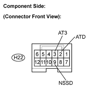
| 2.INSPECT SHIFT LOCK CONTROL UNIT ASSEMBLY |
 |
Connect the park/neutral position switch connector.
Disconnect the transmission control switch connector of shift lock control unit assembly.
Measure the resistance according to the value(s) in the table below when the shift lever is moved to each position.
| Shift position | Tester connection | Specified condition |
| D | 9 - 2 (NSSD - ATD) | Below 1 Ω |
| 3 | 10 kΩ or higher | |
| D | 9 - 3 (NSSD - AT3) | 10 kΩ or higher |
| 3 | Below 1 Ω |
|
| ||||
| OK | |
|
| 3.CHECK HARNESS AND CONNECTOR (PARK/NEUTRAL POSITION SWITCH - TCM) |
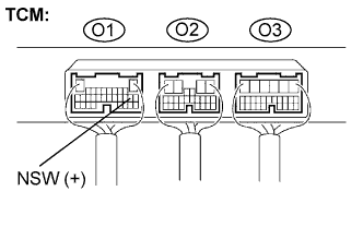 |
Connect the transmission control switch connector of shift lock control unit assembly.
Turn the ignition switch to the ON position, and measure the voltage according to the value(s) in the table below when the shift lever is moved to each position.
| Shift Position | Tester connection | Specified condition |
| P and N | O1-12 (NSW) - Body ground | Below 2 V |
| Except P and N | ↑ | 10 to 14 V |
|
| ||||
| OK | |
|
| 4.CHECK HARNESS AND CONNECTOR (PARK/NEUTRAL POSITION SWITCH - TCM) |
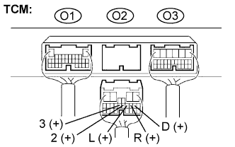 |
Disconnect the TCM connector.
Turn the ignition switch to the ON position, and measure the voltage according to the value(s) in the table below when the shift lever is moved to each position.
| Shift Position | Tester connection | Specified condition |
| R | O2-9 (R) - Body ground | 10 to 14 V* |
| Except R | ↑ | Below 1 V |
| D and 3 | O2-8 (D) - Body ground | 10 to 14 V |
| Except D and 3 | ↑ | Below 1 V |
| 3 | O2-12 (3) - Body ground | 10 to 14 V |
| Except 3 | ↑ | Below 1 V |
| 2 | O2-11 (2) - Body ground | 10 to 14 V |
| Except 2 | ↑ | Below 1 V |
| L | O2-10 (L) - Body ground | 10 to 14 V |
| Except L | ↑ | Below 1 V |
|
| ||||
| OK | ||
 | ||
| ||
