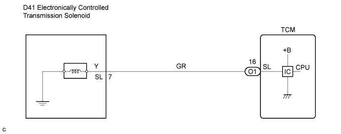
DTC P2769/64 Short in Torque Converter Clutch Solenoid Circuit (Shift Solenoid Valve SL) |
DTC P2770/64 Open in Torque Converter Clutch Solenoid Circuit (Shift Solenoid Valve SL) |
| DTC No. | DTC Detection Condition | Trouble Area |
| P2769/64 | TCM detects short in solenoid valve SL circuit 1 time when solenoid valve SL is operated (1-trip detection logic) |
|
| P2770/64 | TCM detects open in solenoid valve SL circuit 1 time when solenoid valve SL is not operated (1-trip detection logic) |
|
| 1.INSPECT TRANSMISSION WIRE (SL) |
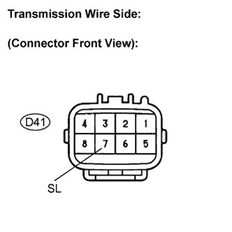 |
Disconnect the transmission wire connector from the transmission.
Measure the resistance according to the value(s) in the table below.
| Tester Connection | Specified Condition 20°C (68°F) |
| 7 - Body ground | 11 to 15 Ω |
|
| ||||
| OK | |
 |
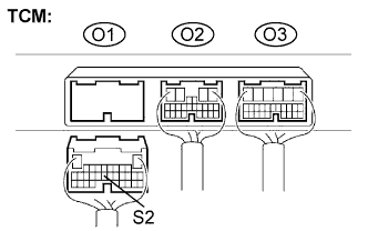
| 2.CHECK HARNESS AND CONNECTOR (TRANSMISSIN WIRE - TCM) |
 |
Connect the transmission connector to the transmission.
Disconnect the connector from the TCM.
Measure the resistance according to the value(s) in the table below.
| Tester Connection | Specified Condition 20°C (68°F) |
| O1-17 (S2) - Body ground | 11 to 15 Ω |
|
| ||||
| OK | ||
 | ||
| ||
| 3.INSPECT SHIFT SOLENOID VALVE SL |
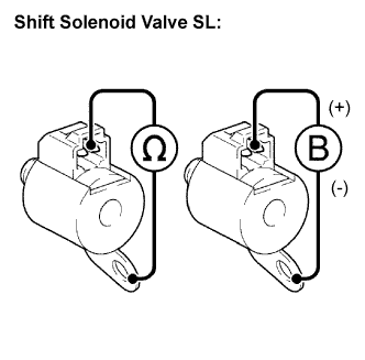 |
Remove the shift solenoid valve SL.
Measure the resistance according to the value(s) in the table below.
| Tester Connection | Specified Condition 20°C (68°F) |
| Solenoid Connector (SR) - Solenoid Body (SR) | 11 to 15 Ω |
Connect the positive (+) lead to the terminal of the solenoid connector, and the negative (-) lead to the solenoid body.
|
| ||||
| OK | ||
| ||
| ||

