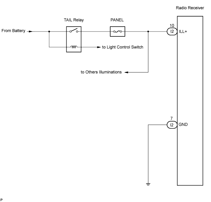
AUDIO AND VISUAL SYSTEM > Illumination Circuit |
| 1.CHECK ILLUMINATION |
Check if the illumination for the radio receiver, A/T shift lever illumination, room light switch, A/C switch or others (blower switch, rear window defogger switch, etc.) comes on when the light control switch is turned to the HEAD or TAIL position.
| Result | Proceed to |
| Illumination comes on for all components except radio receiver. | A |
| No illumination comes on. | B |
|
| ||||
| A | |
 |
| 2.INSPECT RADIO RECEIVER |
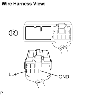 |
Disconnect the radio receiver I2 connector.
Measure the resistance according to the value(s) in the table below.
| Tester connection | Condition | Specified condition |
| GND - Body gorund | Always | Below 1 Ω |
Measure the voltage according to the value(s) in the table below.
| Tester connection | Condition | Specified condition |
| ILL+ - Body ground | Light control SW HEAD or TAIL | 10 to 14 V |
|
| ||||
| OK | ||
 | ||
| ||
