INTEGRATION RELAY > INSPECTION |
| 1. INTEGRATION RELAY |
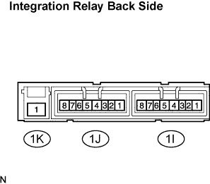 |
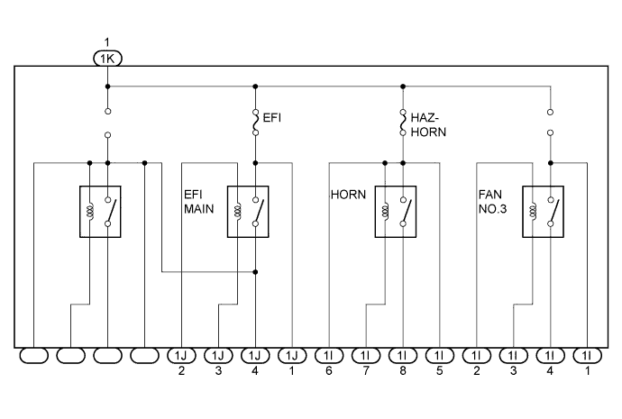
Measure the resistance of the fan No.3 relay.
Using an ohmmeter, measure the resistance according to the value(s) in the table below.
| Tester Connection | Specified Condition |
| 1I-2 ←→ 1I-3 | Approx. 310 Ω |
| 1I-1 ←→ 1I-4 | 10 kΩ or higher |
Connect the battery positive (+) lead to terminal 1I-2 and the negative (-) lead to terminal 1I-3. Using an ohmmeter, measure the resistance according to the value(s) in the table below.
| Tester Connection | Specified Condition |
| 1I-1 ←→ 1I-4 | Below 1 Ω (When battery voltage is applied to terminals 1I-2 and 1I-3) |
|
Measure the resistance of the HORN relay.
Using an ohmmeter, measure the resistance according to the value(s) in the table below.
| Tester Connection | Specified Condition |
| 1I-5 ←→ 1I-7 | Approx. 310 Ω |
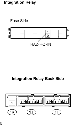 |
Measure the voltage of the HORN relay.
Disconnect the HAZ-HORN fuse. Connect the battery positive (+) lead to terminal HAZ-HORN fuse 2. Using a voltmeter, measure the voltage according to the value(s) in the table below.
| Tester Connection | Specified Condition |
| 1I-5 (+) ←→ negative battery terminal (-) | battery voltage |
| 1I-8 (+) ←→ negative battery terminal (-) | 0V |
Connect the battery negative (-) lead to terminal 1I-7. Using a voltmeter, measure the voltage according to the value(s) in the table below.
| Tester Connection | Specified Condition |
| 1I-8 (+) ←→ negative battery terminal (-) | battery voltage (When battery voltage is applied to terminals HAZ-HORN fuse 2 (+) and 1I-7) |
|
Measure the resistance of the EFI MAIN relay.
Using an ohmmeter, measure the resistance according to the value(s) in the table below.
| Tester Connection | Specified Condition |
| 1J-2 ←→ 1J-3 | Approx. 310 Ω |
| 1J-1 ←→ 1J-4 | 10 kΩ or higher |
Connect the battery positive (+) lead to terminal 1J-2 and the battery negative (-) lead to terminal 1J-3. Using an ohmmeter, measure the resistance according to the value(s) in the table below.
| Tester Connection | Specified Condition |
| 1J-1 ←→ 1J-4 | Below 1 Ω (When battery voltage is applied to terminals 1J-2 and 1J-3) |