 |
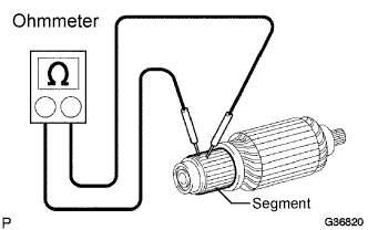
Using an ohmmeter, check that there is continuity between the segments of the commutator.
If there is no continuity between any segment, replace the starter armature.
STARTER (for 2.0 kW Type) > INSPECTION |
| 1. INSPECT STARTER ARMATURE ASSEMBLY |
|
Using an ohmmeter, check that there is continuity between the segments of the commutator.
If there is no continuity between any segment, replace the starter armature.
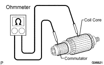 |
Using an ohmmeter, check the resistance between the commutator and armature coil core.
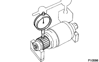 |
Check for the commutator circuit runout.
Place the commutator on V-blocks.
Using a dial indicator, measure the circle runout.
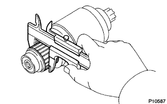 |
Using vernier calipers, measure the commutator diameter.
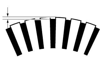 |
Check that the undercut portion between the segments is free of foreign objects and measure its depth.
| 2. INSPECT STARTER YOKE ASSEMBLY |
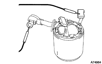 |
Using an ohmmeter, check that there is continuity between the terminal C wire and brushes.
If there is no continuity, replace the starter yoke assembly
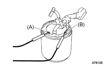 |
Using an ohmmeter, check the resistance between the shunt coil terminals (A) and (B).
| 3. INSPECT STARTER BRUSH HOLDER ASSEMBLY |
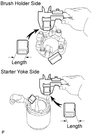 |
Using vernier calipers, measure the brush length.
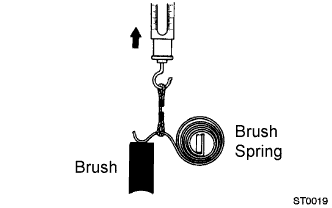 |
Check the pull scale reading as soon as the brush spring is separated from the brush.
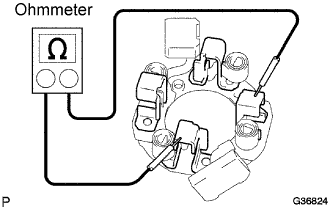 |
Using an ohmmeter, measure the resistance between the positive (+) and negative (-) brush holders.
| 4. INSPECT STARTER CLUTCH SUB-ASSEMBLY |
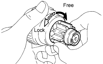 |
Turn the clutch pinion gear clockwise and check that it turns freely. Try to turn the clutch pinion gear counterclockwise and check that it locks. If necessary, replace the starter clutch.
| 5. INSPECT MAGNET STARTER SWITCH ASSEMBLY |
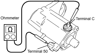 |
Using an ohmmeter, check that there is continuity between terminals 50 and C.
If there is no continuity, replace the magnet starter switch assembly.
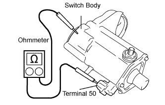 |
Using an ohmmeter, check that there is continuity between terminal 50 and the magnet switch body.
If there is no continuity, replace the magnet starter switch assembly.