Home › ENGINE · 5L-E › STARTING › STARTER (for 2.7kW Type)

STARTER (for 2.7kW Type) > INSPECTION

for Preparation Click here


1. INSPECT STARTER ARMATURE ASSEMBLY


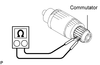
    A112475E02
  1. Check the commutator for an open circuit.

    1. Using an ohmmeter, check that there is continuity between the segments of the commutator.

      1. If there is no continuity between any segment, replace the armature assembly.
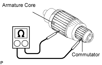


    A112476E01
  1. Check the commutator for a short circuit.

    1. Using an ohmmeter, the resistance between the commutator and armature core.

      Standard:
      10 MΩ or higher

      1. If the result is not as specified, replace the armature assembly.


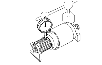
    A102632
  1. Check the commutator circle runout.

    1. Place the armature on the V-blocks.

    2. Using a dial gauge, measure the circle runout.

      Maximum circle runout:
      0.05 mm (0.0020 in.)

      1. If the circle runout is greater than maximum, replace the armature assembly.


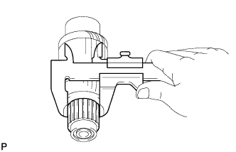
    A112478
  1. Using vernier calipers, measure the commutator diameter.

    Standard diameter:
    36.0 mm (1.417 in.)

    Minimum diameter:
    35.0 mm (1.378 in.)

    1. If the diameter is less than the minimum, replace the armature assembly.


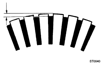
    ST00040
  1. Measure the undercut depth of the commutator.

    Standard depth:
    0.7 mm (0.028 in.)

    Minimum depth:
    0.2 mm (0.008 in.)

    1. If the undercut depth is less than the minimum, correct it with a hacksaw blade.

  1. Inspect the bearings.

    1. Check that the bearing rotates smoothly.

      1. If necessary, replace them.


2. INSPECT STARTER YOKE ASSEMBLY


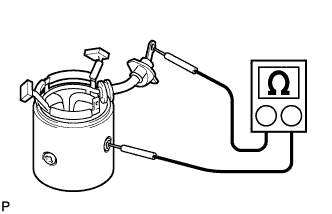
    A112479
  1. Inspect for an open circuit.

    1. Check that there is continuity between the terminal C wire and brushes.

      1. If there is no continuity, replace the starter yoke assembly.


    A112480
  1. Inspect for a short circuit.

    1. Check the continuity between the terminal C wire and starter yoke body.

    2. Check the continuity between the brushes and starter yoke body.

      Standard:
      10 MΩ or higher

      1. If the result is not as specified, replace the starter yoke assembly.


3. INSPECT BRUSH


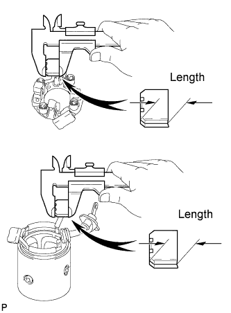
    A112481E03
  1. Using vernier calipers, measure the brush length.

    Standard brush length:
    20.5 mm (0.807 in.)

    Minimum brush length:
    11.0 mm (0.433 in.)

    1. If the length is less than the minimum, replace the brush holder and starter yoke assembly.


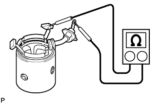
4. INSPECT STARTER BRUSH HOLDER ASSEMBLY


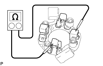
    A112482
  1. Using an ohmmeter, check the continuity between the positive and negative brush holders.

    Standard:
    10 MΩor higher

    1. If the result is not as specified, replace the brush holder assembly.


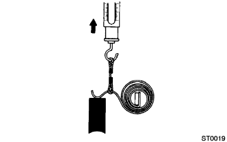
    ST00019
  1. Using a pull scale, measure the brush spring load.

    Standard spring load:
    26 to 45 N (2.7 to 4.6 kgf, 5.8 to 10.1 lbf)

    Minimum spring lord:
    12.4 N (1.3 kgf, 2.8 lbf)

    1. If the spring load is less than the minimum, replace the brush holder assembly.


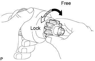
5. INSPECT STARTER CLUTCH SUB-ASSEMBLY


    A112483E01
  1. Check that the starter clutch operates.

    1. If the starter clutch does not operate, replace it.


6. INSPECT MAGNET STARTER SWITCH ASSEMBLY


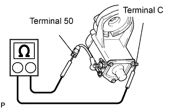
    A112485E03
  1. Check the pull-in coil resistance.

    1. Using an ohmmeter, check that there is continuity between terminals 50 and C.

      1. If there is no continuity, replace the magnet starter switch assembly.


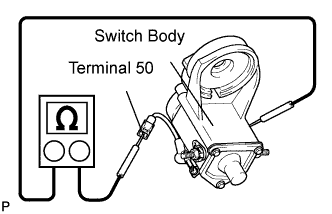
    A112484E03
  1. Check the holding coil resistance.

    1. Using an ohmmeter, check that there is continuity between terminals 50 and switch body.

      1. If there is no continuity, replace the magnet starter switch assembly.