INSTALLATION
Removal / installation · Vehicles built from Dec 2017
Versions by build date: Oct 2014 – Nov 2015 Dec 2015 – Mar 2016 Apr 2016 – Dec 2016 Jan 2017 – Nov 2017 from Dec 2017
| 1.
INSTALL POWER STEERING LINK ASSEMBLY |
 |
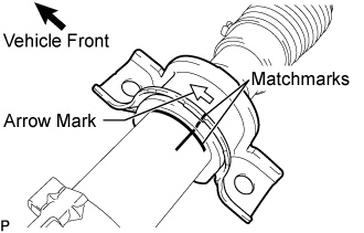
- Align the matchmarks on the steering rack housing bracket No.2, steering rack housing grommet No.2, and the power steering link assembly.
- HINT:
- Make sure that the arrow mark on the steering rack housing bracket No.2 faces toward the front of the vehicle.
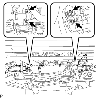
- Install the power steering link assembly with the 4 bolts.
-
Torque:
- 123 N*m{
1254 kgf*cm
, 91 ft.*lbf
}
| 2.
CONNECT PRESSURE FEED TUBE ASSEMBLY |
|
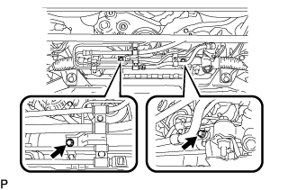
- Install the pressure feed tube clamp to the power steering link assembly with the 2 bolts.
-
Torque:
- 12 N*m{
117 kgf*cm
, 9 ft.*lbf
}
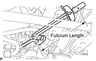
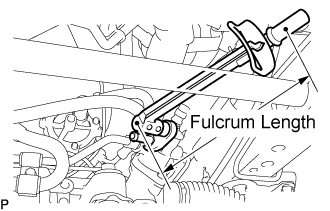
- Using a union nut wrench, connect the pressure feed tube assembly (pressure tube side) to the power steering link assembly.
-
Torque:
- 41 N*m{
413 kgf*cm
, 30 ft.*lbf
}
- NOTICE:
- Use a torque wrench with a fulcrum length of 345 mm (13.58 in.).
- Using a union nut wrench, install the steering gear outlet return tube to the power steering link assembly.
-
Torque:
- 41 N*m{
413 kgf*cm
, 30 ft.*lbf
}
- NOTICE:
- Use a torque wrench with a fulcrum length of 345 mm (13.58 in.).
Connect the pressure feed tube assembly (return tube side) to the steering gear outlet return tube with the clip.
| 3.
CONNECT TIE ROD END SUB-ASSEMBLY LH |
|
Connect the tie rod end sub-assembly LH to the steering knuckle with the nut.
-
Torque:
- 50 N*m{
510 kgf*cm
, 37 ft.*lbf
}
Install a new cotter pin.
- NOTICE:
- Further tighten the nut up to 60° if the holes for the cotter pin are not aligned.
| 4.
CONNECT TIE ROD END SUB-ASSEMBLY RH |
|
- HINT:
- Perform the same procedure as for the LH side.
| 5.
CONNECT STEERING TORQUE SHAFT ASSEMBLY |
|
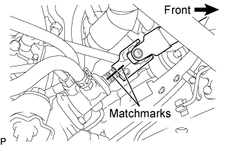
- Align the matchmarks on the steering torque shaft assembly and the power steering link assembly.
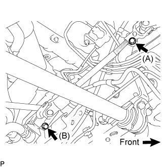
- Install bolt (B) and tighten the 2 bolts.
-
Torque:
- 35 N*m{
360 kgf*cm
, 26 ft.*lbf
}
| 6.
ADD POWER STEERING FLUID |
|
| 7.
BLEED POWER STEERING FLUID |
|
(Click here)
| 8.
CHECK FOR POWER STEERING FLUID LEAKS |
|
| 9.
INSTALL FRONT WHEELS |
|
-
Torque:
- 100 N*m{
1,020 kgf*cm
, 74 ft.*lbf
}
| 10.
PLACE FRONT WHEELS FACING STRAIGHT AHEAD |
|
| 11.
INSTALL ENGINE UNDER COVER NO.1 |
|
| 12.
INSPECT AND ADJUST FRONT WHEEL ALIGNMENT |
|
(Click here)