ON-VEHICLE INSPECTION
Inspection · Vehicles built from Dec 2017
Versions by build date: Oct 2014 – Nov 2017 from Dec 2017
| INSPECT COOLANT |

| INSPECT ENGINE OIL |
| INSPECT BATTERY SPECIFIC GRAVITY |
| INSPECT AIR CLEANER FILTER ELEMENT SUB-ASSEMBLY |
Remove the air cleaner filter element from the air cleaner case sub-assembly.
Visually check that there is no dirt, clog, and damage to the air cleaner filter element.
- HINT:
- If there is any dirt or clog on the air cleaner filter element, clean it with compressed air.
- If any dirt or clog remains even after cleaning the air cleaner element with compressed air, replace it.
- If there is any dirt or clog on the air cleaner filter element, clean it with compressed air.
| INSPECT VANE PUMP V BELT |
Check the V belt deflection.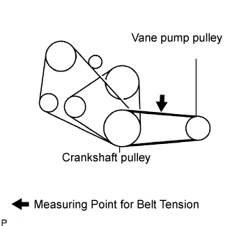

Belt deflection
- Pressing force:
- 98 N (10 kgf, 22 *lbf)
New belt
mm (in.)
Used belt
mm (in.)
7.5 to 9.5
(0.30 to 0.37)
9.0 to 13
(0.35 to 0.51)
Tension
New belt
N (kgf)
Used belt
N (kgf)
441 to 539
(45 to 55)
245 to 343
(25 to 35)
- NOTICE:
- Check the drive belt deflection at the specified point.
- When installing a new belt, set its tension value as specified.
- When checking a belt used for over 5 minutes, confirm the deflection value is within the specified range.
- When reinstalling a belt used for over 5 minutes, perform the check based on the used deflection value.
- V belt tension and deflection value should be checked after two revolution of engine cranking.
- When using a belt tension gauge, confirm the accuracy first by using a master gauge.
- Check the drive belt deflection at the specified point.
| INSPECT V (COOLER COMPRESSOR TO CRANKSHAFT PULLEY) BELT NO.1 (W/ AIR CONDITIONING) |
Check the V belt deflection.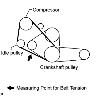
Belt deflection
- Pressing force:
- 98 N (10 kgf, 22 *lbf)
New belt
mm (in.)
Used belt
mm (in.)
11 to 15
(0.43 to 0.59)
15 to 20
(0.59 to 0.79)
Tension
New belt
N (kgf)
Used belt
N (kgf)
372 to 608
(38 to 62)
196 to 392
(20 to 40)
- NOTICE:
- Check the drive belt deflection at the specified point.
- When installing a new belt, set its tension value as specified.
- When checking a belt used for over 5 minutes, confirm the deflection value is within the specified range.
- When reinstalling a belt used for over 5 minutes, perform the check based on the used deflection value.
- V belt tension and deflection value should be checked after two revolution of engine cranking.
- When using a belt tension gauge, confirm the accuracy first by using a master gauge.
- Check the drive belt deflection at the specified point.
| INSPECT FAN & GENERATOR V BELT |
Check the V belt deflection. (Per 1 belt)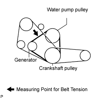
Belt deflection
- Pressing force:
- 98 N (10 kgf, 22 *lbf)
New belt
mm (in.)
Used belt
mm (in.)
7.0 to 10
(0.28 to 0.39)
10 to 14
(0.39 to 0.55)
Tension (Per 1 belt)
New belt
N (kgf)
Used belt
N (kgf)
441 to 539
(45 to 55)
196 to 343
(20 to 35)
- NOTICE:
- Check the drive belt deflection at the specified point.
- When installing a new belt, set its tension value as specified.
- When checking a belt used for over 5 minutes, confirm the deflection value is within the specified range.
- When reinstalling a belt used for over 5 minutes, perform the check based on the used deflection value.
- V belt tension and deflection value should be checked after two revolution of engine cranking.
- When using a belt tension gauge, confirm the accuracy first by using a master gauge.
- Check the drive belt deflection at the specified point.
| INSPECT INJECTION TIMING |
Using a mirror, check that the matchmarks of the injection pump flange and the timing gear case are aligned.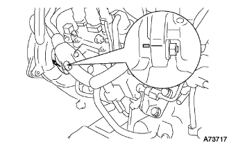
| ADJUST INJECTION TIMING |
Loosen the following nuts and bolts.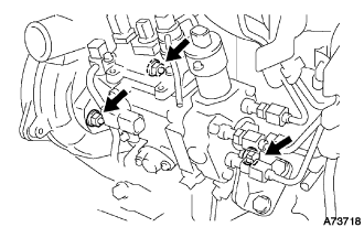
Bolt holding the injection pump to the injection pump stay.
2 nuts holding the injection pump to the timing gear case.
Align the matchmark by slightly tilting the injection pump.
Tighten the following nuts and bolts.
2 nuts holding the injection pump to the timing gear case.
- Torque:
- 21 N*m{ 210 kgf*cm , 15 ft.*lbf }
Bolt holding the injection pump to the injection pump stay.
- Torque:
- 26 N*m{ 270 kgf*cm , 19 ft.*lbf }
| INSPECT ENGINE IDLE SPEED |
Warm up the engine.
When using an intelligent tester:
Connect the intelligent tester to the DLC3.
- Idle speed:
- 720 to 820 rpm (A/C OFF)
750 to 850 rpm (A/C ON)
- HINT:
- Refer to the intelligent tester operator's manual for further details.
When not using an intelligent tester: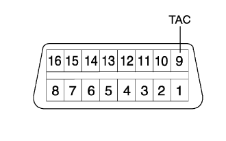
Using SST, connect the tachometer test probe to terminal 9 (TAC) of the DLC3.
- SST
- 09843-18040
Check the idle speed.
- Idle speed:
- 720 to 820 rpm (A/C OFF)
750 to 850 rpm (A/C ON)
- NOTICE:
- Switch off all accessories.
| INSPECT MAXIMUM ENGINE SPEED |
Start the engine.
Depress the accelerator pedal all the way.
Check the maximum speed.
- Maximum speed:
- 4,850 to 4,950 rpm
| INSPECT COMPRESSION |
- HINT:
- If there is a lack of power, excessive oil consumption or poor fuel economy is suspected. Measure the compression pressure.
Warm up and stop the engine.
Remove the glow plugs. (Click here)
Disconnect the spill control valve connector.
Check the cylinder compression pressure.
- HINT:
- Turn the starter before measuring the compression pressure and remove the foreign objects.
Install SST (attachment) to the glow plug hole.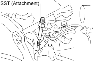
- SST
- 09992-00025
(09992-00121)
- Torque:
- 13 N*m{ 133 kgf*cm , 10 ft.*lbf }
Connect SST (compression gauge) to the SST (attachment).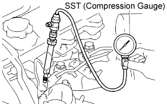
- SST
- 09992-00025
(09992-00211)
Fully open the throttle valve, and start the engine.
While cranking the engine, measure the compression pressure.
- HINT:
- Always use a fully charged battery to obtain engine revolution of 250 rpm or more.
Repeat steps (a) through (d) for each cylinder.
- NOTICE:
- This measurement must be done as quickly as possible.
- Compression pressure:
- 3,138 kPa (32.0 kgf/cm2, 455 psi) or more
- Minimum pressure:
- 1,961 kPa (20.0 kgf/cm2, 284 psi)
- Difference between each cylinder:
- 490 kPa (5.0 kgf/cm2, 71 psi) or less
If the cylinder compression in one or more cylinders is low, pour a small amount of engine oil into the cylinder through the glow plug hole and repeat steps (a) through (d) for the cylinder with low compression.
If adding oil helps the compression, the piston rings and/or cylinder bore may be worn or damaged.
If pressure stays low, a valve may be stuck or the seating may be improper, or there may be leakage past the gasket.
Remove the SST.
Reinstall the glow plugs. (Click here)
Reconnect the spill control valve connector.