REMOVAL
Removal / installation · Vehicles built from Oct 2014
| 1. DISCONNECT CABLE FROM NEGATIVE BATTERY TERMINAL |
| 2. DRAIN MANUAL TRANSMISSION OIL |

Remove the filler plug and gasket.
Remove the drain plug and gasket, and drain the oil.
Install the drain plug with a new gasket.
- Torque:
- 37 N*m{ 377 kgf*cm , 27 ft.*lbf }
| 3. REMOVE EXHAUST PIPE ASSEMBLY FRONT (for Long Wheelbase) |
Remove the 4 bolts, 2 nuts and 2 compression springs. 2 gasket and exhaust pipe assembly front.
Disconnect the exhaust pipe support, and remove the exhaust pipe assembly front and 2 gaskets.
| 4. REMOVE EXHAUST PIPE ASSEMBLY FRONT (for Super Long Wheelbase) |
Remove the 4 bolts, 2 nuts, 2 compression springs. exhaust pipe assembly front and 2 gaskets.
Disconnect the exhaust pipe support, and remove the exhaust pipe assembly front and 2 gaskets.
| 5. REMOVE PROPELLER SHAFT ASSEMBLY (for Long Wheelbase) |
Put matchmarks on both flanges.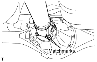

Remove the 4 nuts, bolts and washers.
- HINT:
- If the flange connection is hard to separate, temporarily tighten one nut only and evenly tap the flange with a brass bar and hammer to separate the propeller shaft assembly from the differential companion flange.
Remove the propeller shaft assembly.
Insert SST in the transmission to prevent oil leakage.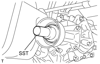
- NOTICE:
- Do not damage the oil seal.
Use the following SST for the automatic transmission
- SST
- 09325-40010
Use the following SST for the manual transmission
- SST
- 09325-20010
| 6. REMOVE PROPELLER WITH CENTER BEARING SHAFT ASSEMBLY (for Super Long Wheelbase) |
Put matchmarks on both flanges.
Remove the 4 nuts, bolts and washers.
- HINT:
- If the flange connection is hard to separate, temporarily tighten one nut only and evenly tap the flange with a brass bar and hammer to separate the propeller with center bearing shaft assembly from the differential companion flange.
Remove the 2 bolts and center support bearing assembly No.1.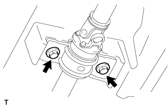
Remove the propeller with center bearing shaft assembly.
Insert SST in the transmission to prevent oil leakage.
- NOTICE:
- Do not damage the oil seal.
Use the following SST for the automatic transmission.
- SST
- 09325-40010
Use the following SST for the manual transmission.
- SST
- 09325-20010
| 7. SEPARATE TRANSMISSION CONTROL CABLE ASSEMBLY |
Put matchmarks on the control cable assembly and the outer lever.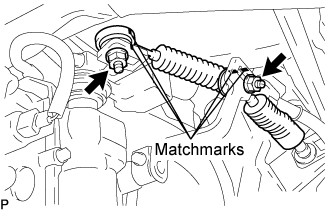
Remove the 2 nuts and separate the transmission control cable from the outer lever.
Using a screwdriver, disengage the claws of the 2 clips.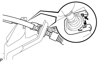
Remove the transmission control cable and 2 clips from the transmission control cable bracket No.1.
| 8. DISCONNECT WIRE HARNESS |
Disconnect the 2 connectors and clamps.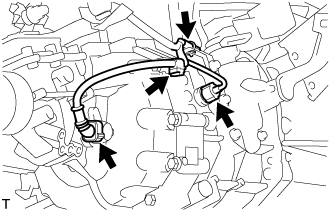
Separate the wire harness clamp from the manual transmission.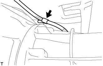
Remove the 2 bolts and separate the ground cable.
| 9. SEPARATE CLUTCH RELEASE CYLINDER ASSEMBLY |
Remove the 2 bolts and separate the clutch release cylinder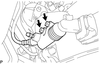
| 10. REMOVE STARTER ASSEMBLY (for 2.0kW Type) |
for Wide Body: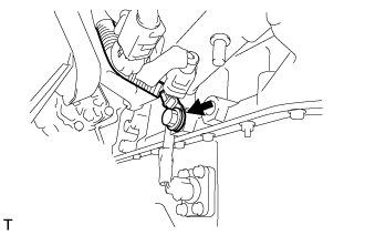
Remove the bolt, then remove the ground cable.
Open the terminal cap.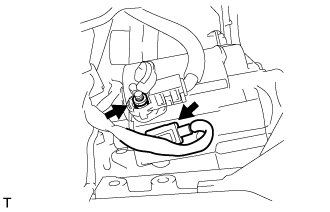
Remove the nut and disconnect the wire harness from terminal 30.
Disconnect the terminal 50 connector from the starter assembly.
Remove the bolt and 2 nuts, then remove the starter.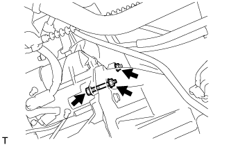
| 11. REMOVE STARTER ASSEMBLY (for 2.2 kW Type) |
Remove the No. 2 terminal cap.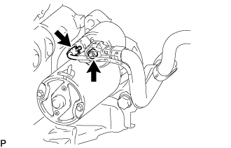
Disconnect the starter connector.
Remove the nut and disconnect the starter wire.
Remove the 2 bolts and disconnect the wiring harness clamp bracket.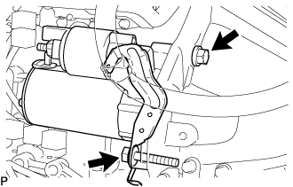
Remove the stater assembly.
| 12. REMOVE STARTER ASSEMBLY (for 2.7 kW Type) |
for Wide Body:
Remove the bolt, then disconnect the ground cable.
Open the terminal cap.
Remove the nut and disconnect the wire harness from terminal 30.
Disconnect the terminal 50 connector from the starter assembly.
Remove the bolt and 2 nuts, then remove the starter.
| 13. REMOVE MANUAL TRANSMISSION UNIT ASSEMBLY |
Support the manual transmission unit with a transmission jack.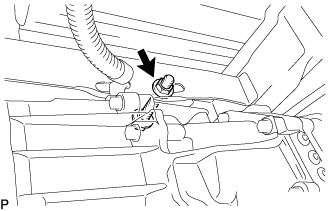
Remove the bolt, nut, and 2 washers, and then separate the transmission unit from the frame.
Remove the 9 bolts, manual transmission unit, control cable bracket No.1, rear end plate, and cylinder block insulator.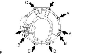
- HINT:
- The A bolts in the illustration tighten the control cable bracket together.
- The A bolts in the illustration tighten the control cable bracket together.
- The B bolts in the illustration tighten the rear end plate together.
- The B bolts in the illustration tighten the rear end plate together.
- Bolt C in the illustration tightens the harness clamp bracket together.
- Bolt C in the illustration tightens the harness clamp bracket together.
| 14. REMOVE EXTENSION HOUSING DYNAMIC(MTM) DAMPER (WITH DYNAMIC DAMPER) |
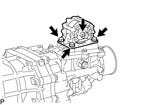
Remove the 4 bolts and extension housing dynamic (MTM) damper.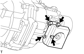
| 15. REMOVE REAR ENGINE MOUNTING INSULATOR ASSEMBLY |
Remove the 4 bolts and rear engine mounting insulator assembly.