REMOVAL
Removal / installation · Vehicles built from Oct 2014
| 1. REMOVE REAR WHEELS |
| 2. DRAIN DIFFERENTIAL OIL |

Remove the filler plug and gasket.
Remove the drain plug and gasket, and drain the oil.
| 3. DRAIN BRAKE FLUID |
| 4. REMOVE REAR BRAKE DRUM SUB-ASSEMBLIES |
Release the parking brake lever, and remove the brake drum.
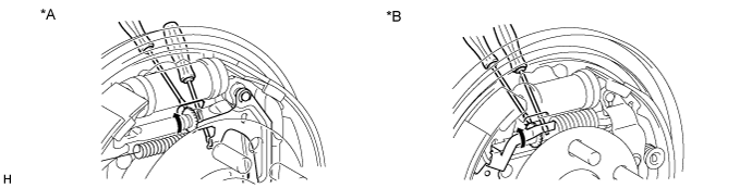

Text in Illustration *A
for 295 mm Drum
*B
for 254 mm Drum
- HINT:
- If the brake drum cannot be removed easily, perform the following steps.
Remove the hole plug and insert a screwdriver through the hole in the backing plate, and hold the automatic adjusting lever away from the adjuster.
Using another screwdriver, contract the brake shoe adjuster by turning the adjusting wheel.
| 5. REMOVE REAR AXLE BRAKE DRUM GASKETS |
| 6. REMOVE AUTOMATIC ADJUST LEVER LH |
for 254 mm drum:
Remove the automatic adjust lever and the tension spring.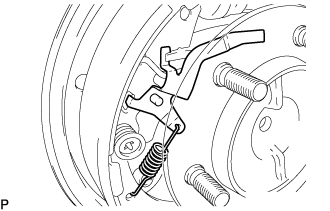
| 7. REMOVE AUTOMATIC ADJUST LEVER RH |
- HINT:
- Removal procedure of the RH side is the same as that of the LH side.
| 8. SEPARATE PARKING BRAKE SHOE STRUT SET LH |
for 254 mm drum:
Using SST, remove the upper side tension spring from the brake shoe.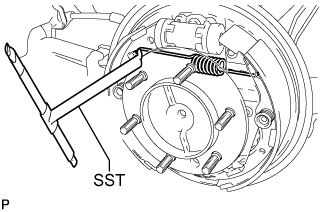
- SST
- 09703-30011
for 295 mm drum:
Using SST, remove the upper side tension spring from the brake shoe.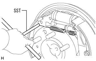
- SST
- 09703-30011
| 9. SEPARATE PARKING BRAKE SHOE STRUT SET RH |
- HINT:
- Removal procedure of the RH side is the same as that of the LH side.
| 10. REMOVE FRONT BRAKE SHOES |
for 254 mm drum:
Using a needle-nose pliers, remove the anchor side tension spring.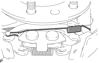
Using SST, remove the cup, shoe hold-down sprig and pin.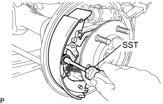
- SST
- 09718-00011
Remove the parking brake shoe lower strut.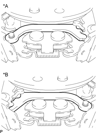
Text in Illustration *A
LH Side
*B
RH Side
Separate the brake shoe return spring, and remove the front brake shoe.
for 295 mm drum:
Using SST, remove the cup, shoe hold-down sprig and pin.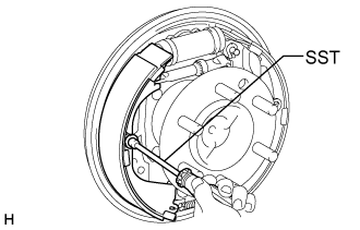
- SST
- 09718-00011
Separate the brake shoe return spring, and remove the front brake shoe.
| 11. REMOVE REAR BRAKE SHOES |
for 254 mm drum:
Using SST, remove the cup, shoe hold-down sprig and pin.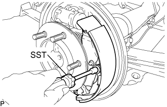
- SST
- 09718-00011
Disconnect the parking brake cable No. 3 and remove the rear brake shoe.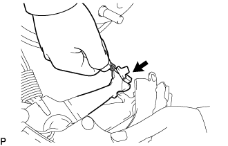
for 295 mm drum:
Using SST, remove the cup, shoe hold-down sprig and pin.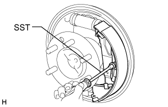
- SST
- 09718-00011
Remove the tension spring.
Disconnect the parking brake cable No. 3 and remove the rear brake shoe.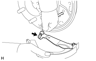
| 12. REMOVE PARKING BRAKE SHOE STRUT SET LH |
for 254 mm drum:
Using a screwdriver, remove the C-washer, brake shoe lever, rear cushion lever and brake shoe strut set from the brake shoe.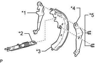
Text in Illustration *1
Brake Shoe Lever
*2
Brake Shoe Strut Set
*3
Rear Brake Shoe
*4
Rear Cushion Lever
*5
C-washer
Remove the adjusting bolt and tension spring from the brake shoe strut set.
for 295 mm drum:
Remove the brake shoe strut set.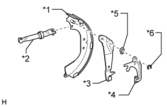
Text in Illustration *1
Rear Brake Shoe
*2
Brake Shoe Strut Set
*3
Brake Shoe Lever
*4
Automatic Adjust Lever
*5
C-washer
*6
E-ring
Using a screwdriver, remove the E-ring and automatic adjust lever.
Using a screwdriver, remove the C-washer and brake shoe lever from the brake shoe.
| 13. REMOVE PARKING BRAKE SHOE STRUT SET RH |
- HINT:
- Removal procedure of the RH side is the same as that of the LH side.
| 14. SEPARATE PARKING BRAKE CABLE ASSEMBLY NO. 3 |
Remove the 2 bolts and separate the parking brake cable assembly No.3 from the backing plate.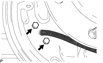
Remove the 5 bolts, nut and parking brake cable assembly No.3.
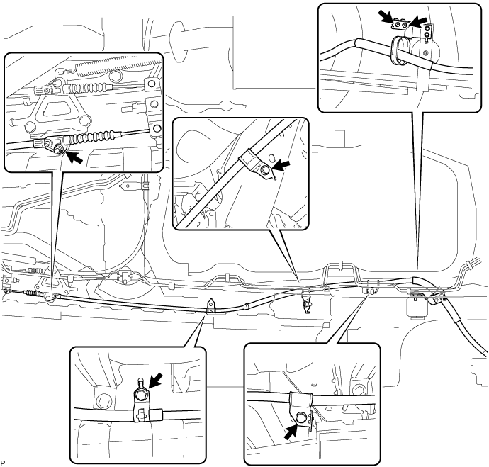
Remove the parking brake cable assembly No.3 from the parking brake equalizer.
| 15. SEPARATE PARKING BRAKE CABLE ASSEMBLY NO. 2 |
- HINT:
- Removal procedure of the RH side is the same as that of the LH side.
| 16. REMOVE REAR WHEEL BRAKE CYLINDER ASSEMBLY LH |
Using a union nut wrench, disconnect the brake tube, use a container to catch brake fluid.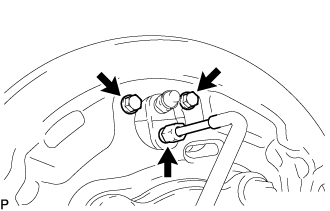
Remove the 2 bolts and wheel cylinder.
| 17. REMOVE REAR WHEEL BRAKE CYLINDER ASSEMBLY RH |
- HINT:
- Removal procedure of the RH side is the same as that of the LH side.
| 18. SEPARATE REAR SPEED SENSOR LH (w/ ABS) |
Disconnect the sensor connector.
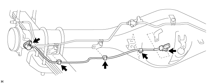
Detach the 4 clamps.
Remove the bolt and rear speed sensor LH.
- NOTICE:
- Prevent foreign matter from attaching to the sensor tip.
Remove the O-ring from the rear speed sensor.
| 19. SEPARATE REAR SPEED SENSOR RH (w/ ABS) |
- HINT:
- Removal procedure of the RH side is the same as that of the LH side.
| 20. REMOVE REAR AXLE SHAFT WITH BACKING PLATE LH |
Remove the 4 nuts and rear axle shaft with backing plate.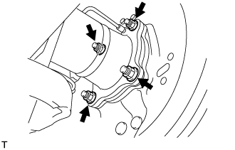
- NOTICE:
- Be careful not to damage the rear axle shaft oil seal.
- Be careful not to damage the skid control rotor rear.
- Be careful not to damage the rear axle shaft oil seal.
| 21. REMOVE REAR AXLE SHAFT WITH BACKING PLATE RH |
- HINT:
- Removal procedure of the RH side is the same as that of the LH side.
| 22. REMOVE BEARING RETAINER O-RINGS |
Remove the bearing retainer O-ring from the rear axle housing assembly.
| 23. REMOVE REAR AXLE SHAFT LH OIL SEAL |
Using SST, remove the rear axle shaft oil seal from the rear axle housing assembly.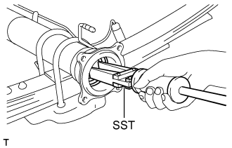
- SST
- 09308-00010
| 24. REMOVE REAR AXLE SHAFT RH OIL SEAL |
- HINT:
- Removal procedure of the RH side is the same as that of the LH side.
| 25. REMOVE PROPELLER SHAFT ASSEMBLY (for Super Long Wheelbase) |
Put matchmarks on both flanges.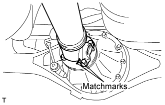
Remove the 4 nuts, bolts and washers.
- HINT:
- If the flange connection is hard to separate, temporarily tighten one nut only and evenly tap the flange with a brass bar and hammer to separate the propeller with center bearing shaft assembly from the differential companion flange.
Remove the 2 bolts and center support bearing assembly No.1.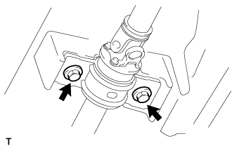
Remove the propeller with center bearing shaft assembly.
Insert SST in the transmission to prevent oil leakage.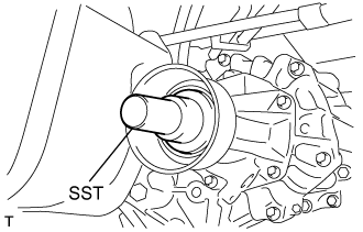
- NOTICE:
- Do not damage the oil seal.
Use the following SST for the automatic transmission.
- SST
- 09325-40010
Use the following SST for the manual transmission.
- SST
- 09325-20010
| 26. REMOVE PROPELLER SHAFT ASSEMBLY (for Long Wheelbase) |
Put matchmarks on both flanges.
Remove the 4 nuts, bolts and washers.
- HINT:
- If the flange connection is hard to separate, temporarily tighten one nut only and evenly tap the flange with a brass bar and hammer to separate the propeller shaft assembly from the differential companion flange.
Remove the propeller shaft assembly.
Insert SST in the transmission to prevent oil leakage.
- NOTICE:
- Do not damage the oil seal.
Use the following SST for the automatic transmission
- SST
- 09325-40010
Use the following SST for the manual transmission
- SST
- 09325-20010
| 27. DISCONNECT LOAD SENSING BRACKET |
Remove the 2 nuts and load sensing bracket.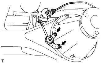
| 28. REMOVE REAR DIFFERENTIAL CARRIER ASSEMBLY |
Support the differential carrier assembly with a jack.
- NOTICE:
- Do not drop the differential carrier assembly
Remove the 10 nuts, washers and differential carrier assembly.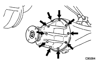
- NOTICE:
- Do not damage the installation surface when removing the differential carrier assembly.
- The remaining oil may leak out when removing the differential carrier assembly.
- Do not damage the installation surface when removing the differential carrier assembly.
| 29. REMOVE REAR DIFFERENTIAL CARRIER GASKET |