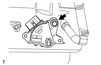
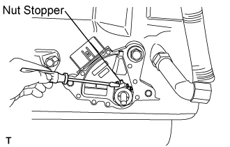
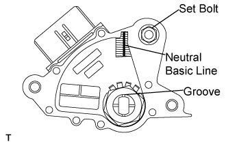
Temporarily tighten the park/neutral position switch assembly with the bolt.
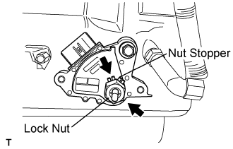
Install the nut stopper and the lock nut.
Torque:
6.9 N*m{
70 kgf*cm
, 61 in.*lbf
}
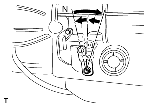
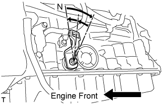
Turn the control shaft lever to a clockwise until it stops, and turn it counter clockwise until 2 notches to set it to the N position.
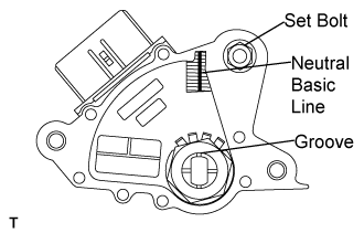
Align the neutral basic line with the switch groove and tighten the adjusting bolt.
Torque:
13 N*m{
130 kgf*cm
, 10 ft.*lbf
}
Using screw driver, bend the tabs of nut stopper.
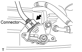
Connect the connector of park/neutral position switch assembly.
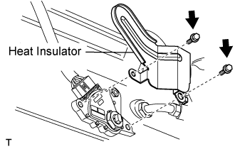
Install the heat insulator to the park/neutral position switch assembly with 2 bolts.
Torque:
7.5 N*m{
76 kgf*cm
, 61 in.*lbf
}
2.
INSTALL TRANSMISSION CONTROL CABLE ASSEMBLY
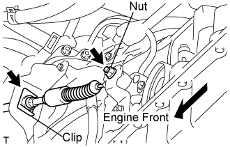
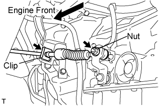
Fix the control cable with a new clip to the control cable bracket.
Install the control cable to the control shaft lever with a nut.
Torque:
15 N*m{
150 kgf*cm
, 11 ft.*lbf
}
3.
CONNECT BATTERY NEGATIVE CABLE
4.
INSPECT SHIFT LEVER POSITION
When shifting from P position only with ignition switch ON and depress the break pedal.
Make sure that the shifting lever moves smoothly and can be moderately operated.
When starting engine, make sure that the vehicle moves forward when shifting from N to D position and moves reward when shifting R position.
5.
ADJUST SHIFT LEVER POSITION
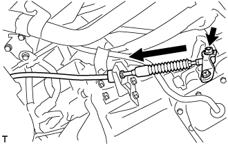
Remove a clip, nut, and disconnect between the control shaft lever to transmission control cable assembly from the control shaft lever and transmission control cable bracket No.1.
Turn the control shaft lever until stop to a clockwise direction, return the control shaft lever 2 notches to N position.
Set the shift lever to N position while holding the shift lever lightly toward the R position side and install it.
Torque:
15 N*m{
150 kgf*cm
, 11 ft.*lbf
}
NOTICE:
Tighten the nut with it closing up cranky.
Inspect the operation condition and work.
6.
INSPECT PARK/NEUTRAL POSITION SWITCH ASSEMBLY
Apply the parking break and turn ignition switch on.
Depress the break pedal and check that the engine starts only when the shift lever is set in N or P position and it does not start in other positions.
Check that the back up light is lit and the reverse warning buzzer sounds only when the shift lever is set in R position and these do not function.
If a failure is found, check the park/neutral position switch for continuity.
7.
ADJUST PARK/NEUTRAL POSITION SWITCH ASSEMBLY
Move the shift lever to the N position.
Loosen the bolt of the park/neutral position switch.