INSTALLATION
Removal / installation · Vehicles built from Jan 2017
Versions by build date: Oct 2014 – Dec 2014 Jan 2015 – Dec 2016 from Jan 2017
| 1. INSTALL LOAD SENSING W/SPRING VALVE ASSEMBLY |

Install the load sensing with spring valve assembly with the 2 bolts.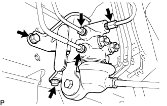

- Torque:
- 32 N*m{ 326 kgf*cm , 24 ft.*lbf }
Using a union nut wrench, install the 3 brake tubes to the load sensing with spring valve assembly.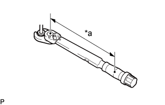
- Torque:
- Specified tightening torque:
- 15 N*m{ 155 kgf*cm , 11 ft.*lbf }
Text in Illustration *a
Torque Wrench Fulcrum Length
- HINT:
- Calculate the torque wrench reading when changing the fulcrum length of the torque wrench (Click here).
- When using a union nut wrench (fulcrum length of 22 mm (0.8661 in.)) + torque wrench (fulcrum length of 162 mm (6.3779 in.)): 13 N*m (137 kgf*cm, 10 ft.*lbf)
- Calculate the torque wrench reading when changing the fulcrum length of the torque wrench (Click here).
Install the load sensing spring bracket with the 2 nuts.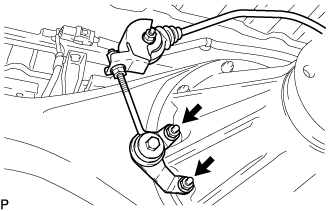
- Torque:
- 13 N*m{ 133 kgf*cm , 10 ft.*lbf }
| 2. ADD BRAKE FLUID |
- Fluid:
- SAE J1703 or FMVSS No. 116 DOT3 or equivalent
- NOTICE:
- Do not remove the filter from the brake master cylinder reservoir and be sure to fill with new brake fluid to avoid any potential contamination of the brake system. Contamination, for example by dirt particles or mineral oil, could lead to functional brake problems.
| 3. BLEED BRAKE LINE |
Connect the vinyl tube to the bleeder plug.
Depress the brake pedal several times and loosen the bleeder plug with the pedal held down.
At the point where the fluid stops coming out, tighten the bleeder plug and release the brake pedal.
Repeat this procedure until the air in the brake fluid is completely bled out.
Tighten the bleeder plug.
Front bleeder plug:
- Torque:
- 11 N*m{ 110 kgf*cm , 8 ft.*lbf }
Rear bleeder plug:
- Torque:
- 11 N*m{ 112 kgf*cm , 8 ft.*lbf }
Repeat the above procedure to bleed the air out of the brake line for each wheel.
| 4. INSPECT BRAKE FLUID LEVEL IN RESERVOIR |
Check the fluid level and add fluid if necessary.
- Fluid:
- SAE J1703 or FMVSS No.116 DOT3 or equivalent
- NOTICE:
- Do not remove the filter from the brake master cylinder reservoir and be sure to fill with new brake fluid to avoid any potential contamination of the brake system. Contamination, for example by dirt particles or mineral oil, could lead to functional brake problems.
| 5. CHECK BRAKE FLUID LEAKAGE |
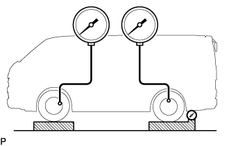
| 6. RAISE FRONT BRAKE PRESSURE 9,807 kPa (100 kgf/cm2, 1,422 psi) AND CHECK REAR BRAKE PRESSURE |
-
-
- HINT:
- Gradually depress on the brake pedal until the pressure reaches the specified valve. Do not overshoot the specified pressure. Read the value of rear pressure 2 seconds after adjusting to the specified fluid pressure.
- Rear brake fluid pressure table:
- Standard body type:
Model
Rear brake pressure
***202R (L) - *E****
5860 +/-800 kPa
(60 +/-8 kgf/cm2, 850 +/-116 psi)
***203R (L) - *E****
5860 +/-800 kPa
(60 +/-8 kgf/cm2, 850 +/-116 psi)
Others
5860 +/-800 kPa
(60 +/-8 kgf/cm2, 850 +/-116 psi)
- Wide long body type:
Model
Rear brake pressure
**H212R (L) - ******
6600 +/-800kPa
(67 +/-8 kgf/cm2, 957 +/-116 psi)
**H213R (L) - ******
6600 +/-800kPa
(67 +/-8 kgf/cm2, 957 +/-116 psi)
- Wide super long body type:
Model
Rear brake pressure
**H220R (L) - ******
6600 +/-800 kPa
(67 +/-8 kgf/cm2, 957 +/-116 psi)
**H221R (L) - ******
6600 +/-800 kPa
(67 +/-8 kgf/cm2, 957 +/-116 psi)
**H22*R - LEMD*N
5500 +/-800 kPa
(56 +/-8 kgf/cm2, 797 +/-116 psi)
**H22*R - LEMN*N
5500 +/-800 kPa
(56 +/-8 kgf/cm2, 797 +/-116 psi)
**H22*R - LEMD*T
5500 +/-800 kPa
(56 +/-8 kgf/cm2, 797 +/-116 psi)
**H22*R (L) - LEM*** (*1)
5500 +/-800 kPa
(56 +/-8 kgf/cm2, 797 +/-116 psi)
Others
6600 +/-800 kPa
(67 +/-8 kgf/cm2, 957 +/-116 psi)
| 7. IF NECESSARY, ADJUST FLUID PRESSURE |
Adjust the length of the shackle.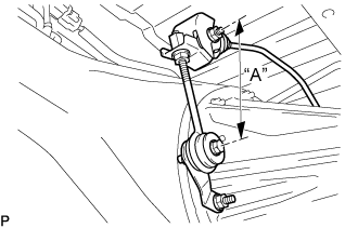
Lower pressure - Lengthen "A"
High pressure - Shorten "A"- Initial set:
- 120 mm (4.72 in.)
- Adjusting:
- 112 to 128 mm (4.40 to 5.04 in.)
If the pressure cannot be adjusted by the shackle, raise or lower the valve body.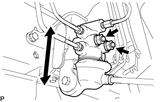
Lower pressure - Lower
High pressure - Raise
Torque the nuts.
- Torque:
- 12.5 N*m (130 kgf*cm, 9 ft.*lbf)
Adjust the length of the shackle again.
If it cannot be adjusted, inspect the valve body.