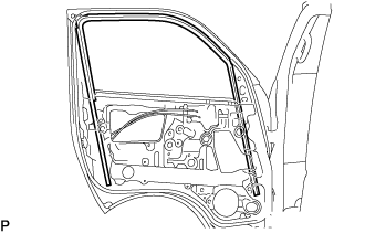
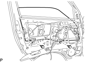
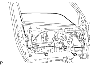
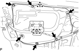
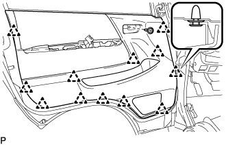
for Cold Area: Attach the 13 clips and remove the front door No. 2 weatherstrip LH.
except Cold Area: Attach the 10 clips and remove the front door No. 2 weatherstrip LH.
2.
INSTALL FRONT DOOR WEATHERSTRIP LH
Attach the 38 clips to install the front door weatherstrip LH.
3.
INSTALL FRONT DOOR CHECK ASSEMBLY LH
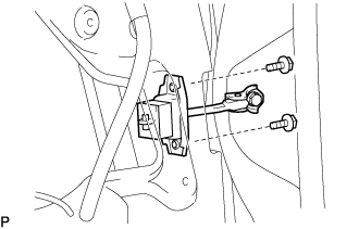
Apply MP grease to the sliding areas of the front door check assembly LH.
Apply adhesive to the threads of the bolt.
Adhesive:
Toyota Genuine Adhesive 1324, Three Bond 1324 or equivalent
Install the front door check assembly LH with the 2 bolts.
Torque:
5.5 N*m{
56 kgf*cm
, 49 in.*lbf
}
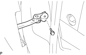
Install the bolt.
Torque:
21 N*m{
214 kgf*cm
, 16 ft.*lbf
}
4.
INSTALL FRONT NO. 1 SPEAKER ASSEMBLY (w/ Front Speaker)
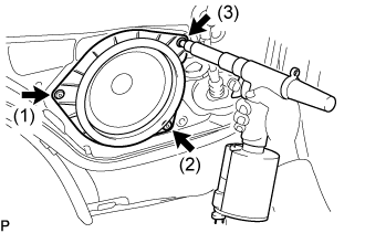
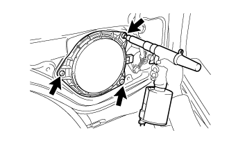
Using an air riveter or hand riveter, install 3 new strike rivets on the front No.1 speaker assembly on the front door panel.
HINT:
Install the new strike rivets in order as shown in the illustration.
NOTICE:
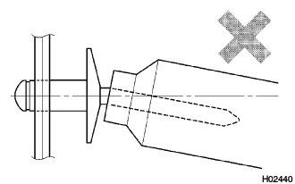
Do not pry the rivet with the riveter, as this will cause damage to the riveter and mandrel.
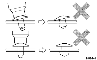
Confirm that the rivets are seated properly against the speaker.
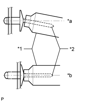
Do not tilt the riveter when installing the rivet to the speaker.
Do not leave any space between the rivet head and speaker.
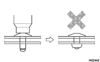
Do not leave any space between the speaker and door. Firmly hold together the 2 items while installing the rivet.
Connect the connector.
5.
INSTALL FRONT SPEAKER COVER (w/o Front Speaker)
Install the front speaker cover to the door.
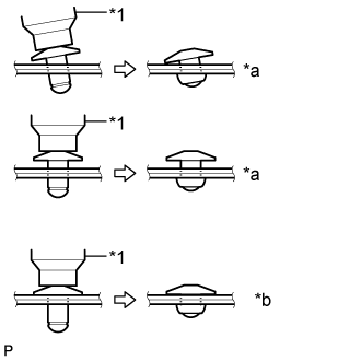
Install a nose piece to an air riveter or hand riveter.
Insert the mandrel part of a new rivet into the nose piece.
Place the riveter upright against the front speaker cover and install the 3 rivets.
HINT:
If the rivet cannot be cut, pull it once and cut it.
NOTICE:
Do not pry the rivet with the riveter as this will cause damage to the riveter and mandrel.
Text in Illustration
*1
Riveter
*2
Mandrel
*a
INCORRECT
*b
CORRECT
Confirm that the rivets are seated properly against the front speaker cover.
Do not tilt the riveter when installing the rivet to the front speaker cover.
Do not leave any space between the rivet head and front speaker cover.
Text in Illustration
*1
Riveter
*a
INCORRECT
*b
CORRECT
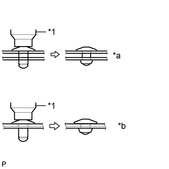
Do not leave any space between the front speaker cover and front door panel. Firmly hold together the 2 items while installing the rivet.
Text in Illustration
*1
Riveter
*a
INCORRECT
*b
CORRECT
Connect the connector.
6.
INSTALL FRONT DOOR NO. 2 SERVICE HOLE COVER LH
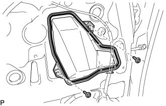
Install the front door No. 2 service hole cover LH with the 2 screws.
7.
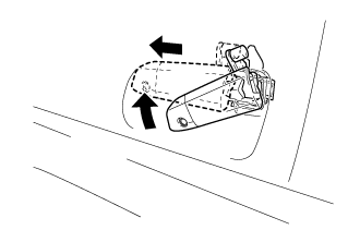
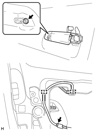
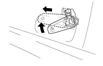
INSTALL FRONT DOOR OUTSIDE HANDLE ASSEMBLY LH (w/ Smart Entry and Start System)
Install the front door outside handle assembly LH by moving it in the direction indicated by the arrow shown in the illustration.
Using a "TORX" socket wrench (T30), install the front door outside handle assembly LH with the "TORX" screw.
Torque:
7.0 N*m{
71 kgf*cm
, 62 in.*lbf
}
Attach the 2 clamps.
Connect the connector.
8.
INSTALL FRONT DOOR OUTSIDE HANDLE ASSEMBLY LH (w/o Smart Entry and Start System)
Install the front door outside handle assembly LH by moving it in the direction indicated by the arrow shown in the illustration.
Using a "TORX" socket wrench (T30), install the front door outside handle assembly LH with the "TORX" screw.
Torque:
7.0 N*m{
71 kgf*cm
, 62 in.*lbf
}
9.
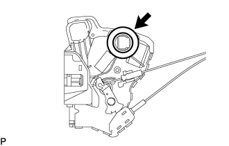
INSTALL FRONT DOOR LOCK ASSEMBLY LH
Apply body grease to the sliding parts on the front door lock assembly LH.
Install a new door lock wire harness.
NOTICE:
When reusing the removed front door lock assembly LH, replace the door lock wire harness sealing on the connector with a new one.
Do not allow grease or dust to adhere to the door lock wire harness sealing surface of the connector.
Reusing the door lock wire harness sealing and/or using the damaged door lock wire harness sealing may cause water intrusion to the connection, and result in a malfunction of the front door lock assembly LH.
Insert the front door outside handle link to the front door lock assembly LH, and set it to the front door panel.
Make sure that the front door outside handle link is securely connected to the front door lock assembly LH.
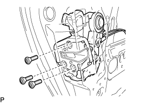
Using a "TORX" socket wrench (T30), install the front door outside handle lock assembly with the 3 "TORX" screws.
Torque:
5.0 N*m{
51 kgf*cm
, 44 in.*lbf
}
10.
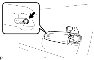
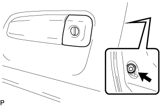
INSTALL FRONT DOOR OUTSIDE HANDLE COVER LH
w/ door lock key cylinder
Using a "TORX" socket wrench (T30), install the front door outside handle cover LH (with the door lock key cylinder installed) with the "TORX" screw.
Torque:
7.0 N*m{
71 kgf*cm
, 62 in.*lbf
}
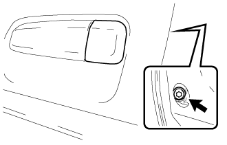
w/o door lock key cylinder
Using a "TORX" socket wrench (T30), install the front door outside handle cover LH with the "TORX" screw.
Torque:
7.0 N*m{
71 kgf*cm
, 62 in.*lbf
}
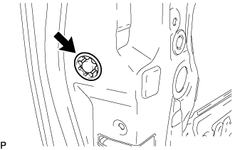
Install the plug hole.
11.
INSTALL FRONT DOOR INSIDE HANDLE SUB-ASSEMBLY LH
Attach the 3 claws to install the front door inside handle sub-assembly LH.
12.
INSTALL FRONT DOOR REAR LOWER FRAME SUB-ASSEMBLY LH
Install the front door rear lower frame sub-assembly LH with the bolt.
13.
INSTALL FRONT DOOR GLASS RUN LH
Install the front door glass run LH.
14.
INSTALL POWER WINDOW REGULATOR MOTOR ASSEMBLY LH (w/ Power Window)
NOTICE:
The regulator arm must be below the intermediate position when installing the power window regulator motor assembly LH.
Apply body grease to the sliding parts on the power window regulator motor assembly LH.
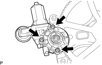
Using a "TORX" socket wrench, install the power window regulator motor assembly LH with the 3 "TORX" screws.
Torque:
5.4 N*m{
55 kgf*cm
, 48 in.*lbf
}
HINT:
The new front window regulator adopts a self-tapping method. The installation position of the regulator will be threaded when the self-tapping screw is inserted.
15.
INSTALL FRONT DOOR WINDOW REGULATOR ASSEMBLY LH (w/ Power Window)
Apply body grease to the sliding parts on the front door window regulator assembly LH.
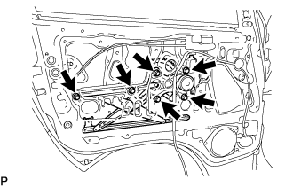
Install the front door window regulator assembly LH with the 6 bolts.
Torque:
8.0 N*m{
82 kgf*cm
, 71 in.*lbf
}
Connect the connector.
16.
INSTALL FRONT DOOR WINDOW REGULATOR ASSEMBLY LH (w/o Power Window)
Apply body grease to the sliding parts on the front door window regulator assembly LH.
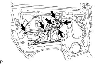
Install the front door window regulator assembly LH with the 6 bolts.
Torque:
8.0 N*m{
82 kgf*cm
, 71 in.*lbf
}
17.
INSTALL FRONT DOOR GLASS SUB-ASSEMBLY LH (w/ Power Window)
Connect the front door glass sub-assembly LH to the bracket on the front door window regulator assembly LH.
NOTICE:
If the front door glass cannot be installed, connect the power window regulator master switch assembly, and manually adjust the glass position up and down.
Install the front door glass sub-assembly LH with the 2 bolts.
Torque:
7.0 N*m{
71 kgf*cm
, 62 in.*lbf
}
Install the plug hole.
18.
INSTALL FRONT DOOR GLASS SUB-ASSEMBLY LH (w/o Power Window)
Connect the front door glass sub-assembly LH to the bracket on the front door window regulator assembly LH.
NOTICE:
If the front door glass cannot be installed, install the front door window regulator handle assembly, and manually adjust the glass position up and down.
Install the front door glass sub-assembly LH with the 2 bolts.
Torque:
7.0 N*m{
71 kgf*cm
, 62 in.*lbf
}
Install the plug hole.
19.
INSTALL FRONT DOOR OUTER GLASS WEATHERSTRIP ASSEMBLY LH
20.
INSTALL FRONT DOOR SERVICE HOLE COVER LH
Attach the clip.
Install the front door service hole cover LH with the 6 bolts.
NOTICE:
If the EPT sealer is torn, replace it with a new one.
Attach the clamp and connect the connector.
21.
INSTALL OUTER REAR VIEW MIRROR ASSEMBLY LH
w/o Retract Mirror:
Install the 3 nuts and outer rear view mirror assembly LH.
Torque:
8.0 N*m{
82 kgf*cm
, 71 in.*lbf
}
w/ Retract Mirror:
Attach the clamp to install the 3 nuts.
Torque:
8.0 N*m{
82 kgf*cm
, 71 in.*lbf
}
Connect the connector to install the outer rear view mirror assembly LH.
22.
INSTALL FRONT DOOR TRIM BOARD SUB-ASSEMBLY LH (w/ Power Window)
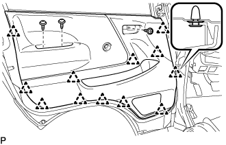
Attach the 12 clips and install the front door trim board sub-assembly LH with the screw.
23.
INSTALL FRONT DOOR TRIM BOARD SUB-ASSEMBLY LH (w/o Power Window)
Attach the 12 clips and install the front door trim board sub-assembly LH with the 3 screws.
24.
INSTALL POWER WINDOW REGULATOR MASTER SWITCH ASSEMBLY (w/ Power Window)
Connect the connector.
Attach the 3 clips and 4 claws and install the power window regulator master switch assembly with the 2 screws.
25.
INSTALL FRONT DOOR WINDOW REGULATOR HANDLE ASSEMBLY (w/o Power Window)
Temporarily install the front door window regulator handle assembly, and completely close the front door glass.
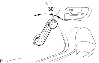
Install the front door window regulator handle assembly with front door window regulator handle shaft snap ring at the angle shown in the illustration.
26.
INSTALL FRONT DOOR LOWER FRAME BRACKET GARNISH LH
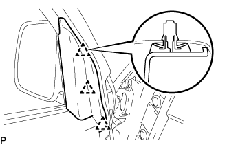
Attach the 3 clips to install the front door lower frame bracket garnish LH.