REMOVAL
Removal / installation · Vehicles built from Jan 2017
Versions by build date: Oct 2014 – Dec 2016 from Jan 2017
| 1.
DISCONNECT BATTERY NEGATIVE CABLE |
|
| 2.
REMOVE ENGINE UNDER COVER NO.1 |
|
| 3.
REMOVE FRONT DOOR SCUFF PLATE RH |
|
| 4.
REMOVE FRONT SEAT ASSEMBLY RH (for Hi-back Seat Type) |
 |
(Click here)
- HINT:
- Perform the same procedure as RH side on the LH side.
| 5.
REMOVE FRONT SEAT ASSEMBLY RH (for Low-back Seat Type) |
|
(Click here)
- HINT:
- Perform the same procedure as RH side on the LH side.
| 6.
REMOVE ENGINE SERVICE HOLE SUB COVER SUB-ASSEMBLY
|
|
Roll up the carpet, and remove the engine service hole sub cover assembly.
| 7.
REMOVE FENDER APRON MUDGUARD SEAL RH |
|
| 8.
REMOVE FAN & GENERATOR V BELT
|
|
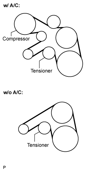
- Remove the drive belt by rotating the tensioner pulley in clockwise direction to loosen its tension with the pulley set bolt of the tensioner.
| 9.
SEPARATE COMPRESSOR AND MAGNETIC CLUTCH (w/ Air Conditioning System)
|
|
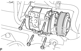
Disconnect the connector.
- Remove the 4 bolts and compressor and magnetic clutch.
| 10.
REMOVE AIR TUBE ASSEMBLY |
|
Remove the 2 clamps, 2 bolts and air tube assembly.
| 11.
REMOVE AIR CLEANER HOSE ASSEMBLY |
|
Remove the bolt and air cleaner hose assembly.
| 12.
REMOVE COMPRESSOR OUTLET ELBOW
|
|
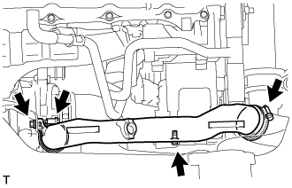
- Remove the 2 bolts and 2 clamps, then remove the compressor outlet elbow.
| 13.
REMOVE IDLE PULLEY ASSEMBLY (w/ Air Conditioning System)
|
|
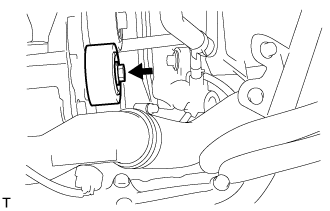
- Remove the bolt and washer, then remove the idle No.2 pulley assembly.
| 14.
REMOVE GENERATOR BRACKET
|
|
- Remove the 2 bolts, then remove the generator bracket.
| 15.
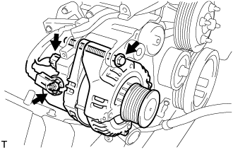
REMOVE GENERATOR ASSEMBLY
|
|
- Disconnect the generator connector.
Remove the terminal cap.
Remove the nut and disconnect the wire harness from terminal B.
Remove the bolt and generator assembly.
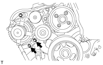
| 16.
REMOVE V-RIBBED BELT TENSIONER ASSEMBLY
|
|
Remove the 4 bolts and belt tensioner assembly.
| 17.
REMOVE FAN PULLEY |
|
Remove the 4 nuts, 4 washer and fan pulley.
| 18.
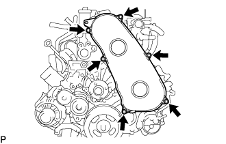
REMOVE TIMING BELT COVER NO.1
|
|
Remove the wire harness clamp.
- Remove the 6 bolts and timing belt cover No.1.
| 19.
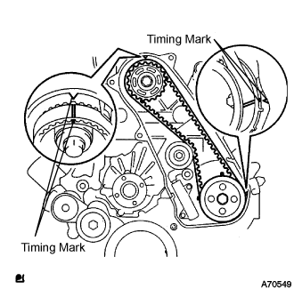
REMOVE TIMING BELT
|
|
- Turn the crankshaft in the clockwise direction and align the timing marks as shown in the illustration.
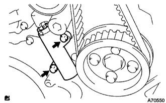
- Uniformly loosen the 2 bolts, and remove the chain tensioner assembly No.1.
Remove the timing belt.
| 20.
DISCONNECT VANE PUMP OIL RESERVOIR ASSEMBLY
|
|
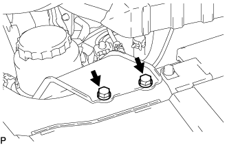
- Remove the 2 bolts and vane pump oil reservoir assembly.
- NOTICE:
- Suspend the vane pump oil reservoir assembly with wire to prevent power steering fluid from spilling out.
| 21.
DISCONNECT OIL RETURN HOSE (w/ Intercooler) |
|
| 22.
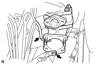
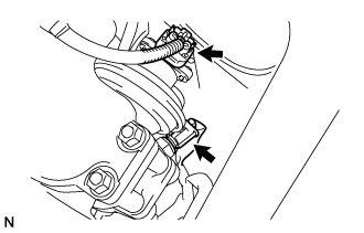
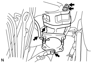
REMOVE EGR PIPE SUB-ASSEMBLY NO.1 (w/ EGR Valve)
|
|
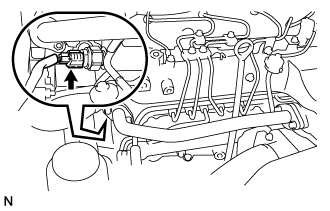
- Disconnect the fuel pressure sensor connector.
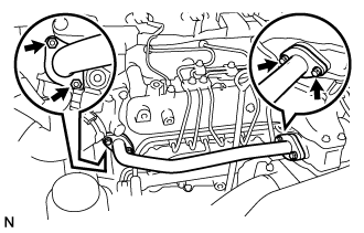
- Remove the 2 bolts, 2 nuts, and the EGR pipe sub-assembly.
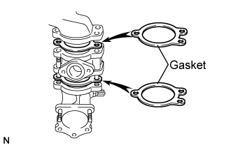
Remove the 2 gaskets.
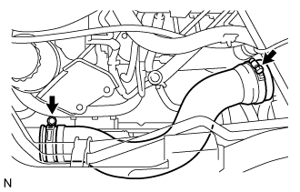
| 23.
REMOVE AIR HOSE NO.4
|
|
- Loosen the 2 clamps.
Remove the air hose No.4.
| 24.
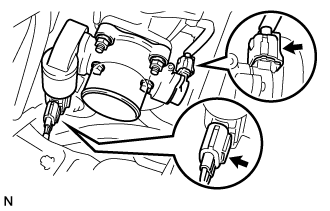
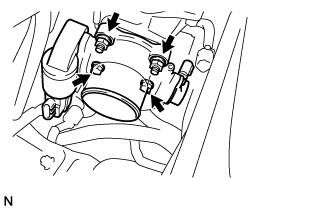
REMOVE DIESEL THROTTLE BODY ASSEMBLY
|
|
- Disconnect the 2 throttle body connectors.
- Remove the 2 bolts, 2 nuts, and the diesel throttle body assembly.
Remove the gasket from intake air connector.
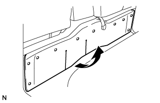
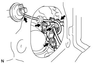
| 25.
REMOVE ENGINE SERVICE HOLE COVER NO.2
|
|
- Roll up the carpet.
Remove the 3 bolts and the engine service hole cover No.2.
| 26.
REMOVE ELECTRIC EGR CONTROL VALVE ASSEMBLY (w/ EGR Valve)
|
|
Remove the vacuum regulating valve.
- Remove the 2 vacuum hoses and the vacuum regulating valve connector.
Remove the 2 bolts and the vacuum regulating valve.
Remove the EGR valve assembly with the sensor.
- Remove the bolt, and separate the manifold stay.
Disconnect the vacuum hose from the intake air connector.
- Disconnect the intake air temperature sensor connector.
Disconnect the EGR valve position sensor connector.
- Remove the bolt, 2 nuts and the intake air connector assembly.
Remove the 2 gaskets and EGR valve assembly from the intake air connector.
| 27.
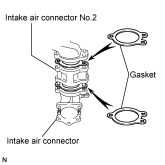
REMOVE INTAKE AIR CONNECTOR (w/o EGR Valve)
|
|
- Remove the bolt, and separate the manifold stay.
Disconnect the vacuum hose from intake air connector.
- Remove the bolt, 2 nuts and the intake air connector assembly.
Remove the 2 gaskets and intake air connector No.2 from the intake air connector.
| 28.
REMOVE OIL LEVEL GAGE GUIDE
|
|
Remove the oil level gauge.
Remove the bolt and oil level gauge guide.
| 29.
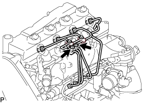
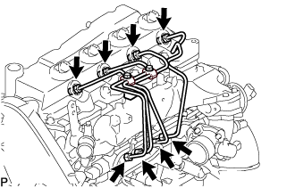
REMOVE INJECTION PIPE
|
|
- SST
- 09023-12701
Remove the injection pipe.
- Remove the 2 nuts and injection pipe clamp No.3.
- Using SST, remove the 4 injection pipes.
- SST
- 09023-12701
| 30.
REMOVE FUEL INLET PIPE SUB-ASSEMBLY
|
|
Using SST, remove the fuel inlet pipe sub-assembly.
- SST
- 09023-12701
| 31.
REMOVE CYLINDER HEAD COVER SUB-ASSEMBLY
|
|
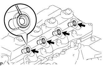
- Using a small screwdriver, remove the holder seal by prying the portion between the holder seal and the cutout part of the cylinder head.
Disconnect the ventilation hose.
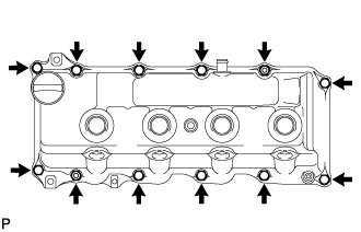
- Remove the 10 bolts, 2 nuts, cylinder head cover and the cylinder head cover gasket.
- NOTICE:
- After removing the fuel pipe, put a plastic bag and rubber band to prevent dirt and foreign objects over the injectors inlet.
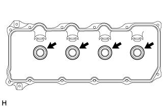
- Remove the 4 No. 3 cylinder head cover gaskets from the cylinder head cover.
| 32.
REMOVE CAMSHAFT TIMING PULLEY
|
|
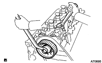
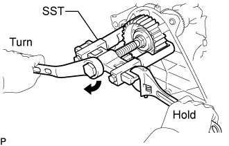
- Remove the bolt for the camshaft timing pulley while holding the camshaft with a monkey wrench.
- Using SST, remove the camshaft timing pulley.
- SST
- 09950-40011
(09951-04010, 09952-04010, 09953-05010, 09957-04010)
09955-04150
| 33.
REMOVE TIMING BELT IDLER SUB-ASSEMBLY NO.1
|
|
- Remove the bolt for the camshaft timing pulley while holding the camshaft with a monkey wrench.
- Using SST, remove the camshaft timing pulley.
- SST
- 09950-40011
(09951-04010, 09952-04010, 09953-05010, 09957-04010)
09955-04150
| 34.
REMOVE TIMING BELT COVER NO.2
|
|
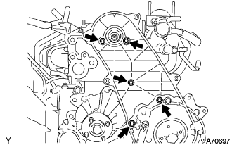
- Remove the 4 bolts and nuts, then remove the timing belt No.2 cover.
| 35.
REMOVE WATER PUMP ASSEMBLY |
|
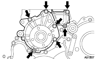
- Remove the 5 bolts, 2 nuts and water pump assembly.