INSTALLATION
Removal / installation · Vehicles built Jan 2015 – Mar 2016
Versions by build date: Oct 2014 – Dec 2014 Jan 2015 – Mar 2016 Apr 2016 – Dec 2016 from Jan 2017
- HINT:
- w/ Dual VVT-i:
- Perform "Inspection After Repairs" after replacing the fuel injector assembly (Click here).
| 1. INSTALL FUEL INJECTOR ASSEMBLY |

- HINT:
- w/ Dual VVT-i:
- Perform "Inspection After Repairs" after replacing the fuel injector assembly (Click here).
Apply a light coat of gasoline or spindle oil to new O-rings, and then install one onto each fuel injector assembly.
Apply a light coat of gasoline or spindle oil to the contact surfaces of the fuel delivery pipe sub-assembly and the O-ring of the fuel injector assembly.
Apply a light coat of gasoline or spindle oil to the O-ring again, and then install the fuel injector assembly into the fuel delivery pipe sub-assembly by turning it right and left.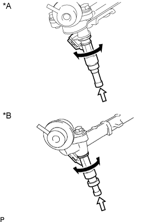

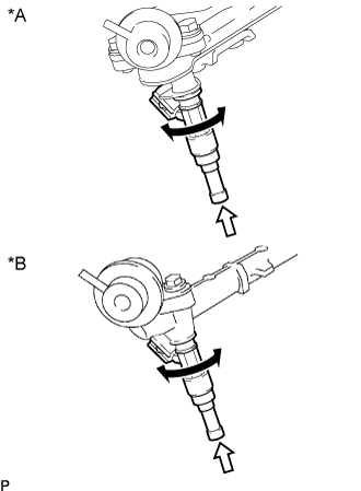
Text in Illustration *A
w/ Dual VVT-i
*B
w/o Dual VVT-i

Turn

Push
- NOTICE:
- Be careful not to twist the O-ring.
- After installing the fuel injector assembly, check that it turns smoothly. If not, reinstall it with a new O-ring.
- Be careful not to twist the O-ring.
| 2. INSTALL FUEL DELIVERY PIPE SUB-ASSEMBLY |
Apply a light coat of gasoline or spindle oil to new O-rings and install them to the injector spacers.
- NOTICE:
- Make sure that the O-rings are installed between the parts correctly.
Install the 4 injector spacers to the cylinder head sub-assembly.
Install 4 new injector vibration insulators to the cylinder head sub-assembly.
Install the 2 No. 1 delivery pipe spacers to the cylinder head sub-assembly.
Temporarily install the fuel delivery pipe sub-assembly together with the 4 fuel injector assemblies with the 2 bolts.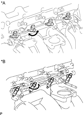
Text in Illustration *A
w/ Dual VVT-i
*B
w/o Dual VVT-i
- NOTICE:
- Do not drop the fuel injector assemblies when installing the fuel delivery pipe sub-assembly.
- Make sure that the fuel injector assembly turns smoothly.
- Do not drop the fuel injector assemblies when installing the fuel delivery pipe sub-assembly.
Tighten the 2 bolts.
- Torque:
- 12 N*m{ 122 kgf*cm , 9 ft.*lbf }
Apply a light coat of gasoline or spindle oil to a new O-ring.
Install the fuel pressure pulsation damper assembly with the 2 bolts.
- Torque:
- 9.0 N*m{ 92 kgf*cm , 80 in.*lbf }
Connect the 4 fuel injector connectors.
Connect the No. 2 fuel hose to the fuel pressure regulator assembly, and slide the clamp to secure the hose.
Connect the vacuum hose to the fuel pressure regulator assembly.
| 3. INSTALL NO. 1 FUEL HOSE |
Connect the No. 1 fuel hose to the fuel pressure pulsation damper assembly (Click here).
| 4. INSTALL THROTTLE BODY ASSEMBLY |
| 5. CONNECT CABLE TO NEGATIVE BATTERY TERMINAL |
- NOTICE:
- When disconnecting the cable, some systems need to be initialized after the cable is reconnected (Click here).
| 6. INSPECT FOR FUEL LEAKS |
Make sure that there are no fuel leaks after performing maintenance on the fuel system.
Connect the GTS to the DLC3.
Turn the ignition switch to ON and turn the GTS on.
- NOTICE:
- Do not start the engine.
Enter the following menus: Powertrain / Engine and ECT / Active Test / Control the Fuel Pump / Speed.
Check that there are no fuel leaks from the fuel system.
If there are fuel leaks, repair or replace parts as necessary.Turn the ignition switch off.
Disconnect the GTS from the DLC3.