INSTALLATION
Removal / installation · Vehicles built Jan 2015 – Nov 2015
Versions by build date: Oct 2014 – Dec 2014 Jan 2015 – Nov 2015 Dec 2015 – Mar 2016 Apr 2016 – Dec 2016 Jan 2017 – Nov 2017 from Dec 2017
| 1.
INSTALL FRONT NO.1 STABILIZER BRACKET |
 |
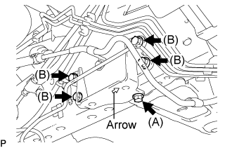
Install the front No.1 stabilizer bracket.
- Temporarily tighten the bolt (A) until front No.1 stabilizer bracket sits in position.
Install the 4 bolts (B) and then fully tighten the bolt (A).
-
Torque:
- 36 N*m{
367 kgf*cm
, 27 ft.*lbf
}
- NOTICE:
- The stamped arrow must point toward the front of the vehicle.
- Tighten the 4 bolts (B) before fully tightening bolt (A).
| 2.
INSTALL FRONT NO.1 STABILIZER BAR BUSHING |
|
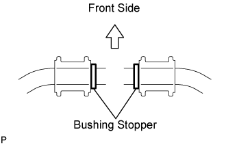
- Install the 2 front No.1 stabilizer bar bushings to the outer side of the bushing stopper on the stabilizer bar.
- HINT:
- The protrusions on front No.1 stabilizer bar bush must be on the stopper side.
| 3.
INSTALL FRONT STABILIZER BAR |
|
Install the front stabilizer bar to the vehicle.
| 4.
INSTALL FRONT NO.2 STABILIZER BRACKET LH |
|
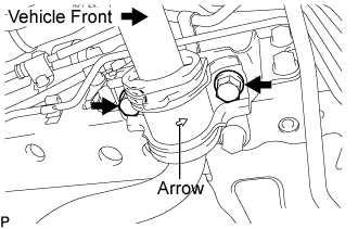
- Install the front No.2 stabilizer bracket LH with the 2 bolts.
-
Torque:
- 36 N*m{
367 kgf*cm
, 27 ft.*lbf
}
- NOTICE:
- Direct the stamped arrow toward the vehicle front.
| 5.
INSTALL FRONT NO.2 STABILIZER BRACKET RH |
|
- HINT:
- Use the same procedures for the LH side.
| 6.
INSTALL FRONT STABILIZER LINK ASSEMBLY LH |
|
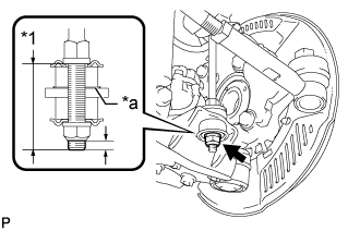
Install the 2 retainers and cushion.
Connect the stabilizer bar link to the front suspension lower arm.
Install the cushion and retainer to the front suspension lower arm.
- Install and tighten a new lock nut until the protrusion length of the thread is the standard length.
- Standard:
- 5 +- 1 mm (0.20 +- 0.04 in.) (Type A)
- 13 +- 1 mm (0.51 +- 0.04 in.) (Type B)
Text in Illustration
*1
|
Type A (50.3 mm (1.98 in.))
Type B (58.3 mm (2.30 in.))
|
*a
|
The retainer can be installed to either the upper or lower surface of the front suspension lower arm.
|
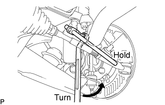
- Install the front stabilizer link assembly LH to the front stabilizer bar with the nut.
-
Torque:
- 80 N*m{
816 kgf*cm
, 59 ft.*lbf
}
- HINT:
- If the stud bolt rotates with the nut, use a hexagon wrench (6 mm) to hold the stud bolt.
| 7.
INSTALL FRONT STABILIZER LINK ASSEMBLY RH |
|
- HINT:
- Use the same procedures for the LH side.
| 8.
INSTALL FRONT WHEEL |
|
-
Torque:
- 100 N*m{
1,020 kgf*cm
, 74 ft.*lbf
}
| 9.
INSPECT AND ADJUST FRONT WHEEL ALIGNMENT |
|
(Click here)