TERMINALS OF ECU
System information · Vehicles built from Oct 2014
| CHECK BACK DOOR CLOSER RELAY |
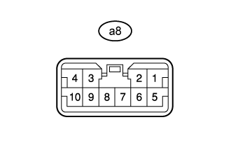  |
Disconnect the a8 back door closer relay connector.
Measure the resistance and voltage according to the value(s) in the table below.
Terminal No. (Symbol)
Wiring Color
Terminal Description
Condition
Specified Condition
a8-7 (E) - Body ground
W-B - Body ground
Ground
Always
Below 1 Ω
a8-5 (L) - Body ground
W - Body ground
Battery power supply
Always
11 to 14 V
Reconnect the a8 back door closer relay connector.
Measure the voltage according to the value(s) in the table below.
Terminal No. (Symbol)
Wiring Color
Terminal Description
Condition
Specified Condition
a8-3 (P/W) - a8-7 (E)
W - W-B
Back door lock assembly (half latch switch) signal circuit
Back door open → back door ajar → back door fully closed
Below 1 V → 11 to 14 V → 11 to 14 V
a8-9 (SIG) - a8-7 (E)
V - W-B
Back door lock assembly (latch switch) signal circuit
Back door open → back door ajar → back door fully closed
Below 1 V → 11 to 14 V → Below 1 V
a8-2 (UL1) - a8-7 (E)
L - W-B
Back door lock assembly (back door lock motor) circuit
Back door open → back door closer motor assembly normal operation → back door closer motor assembly return operation → back door closer motor assembly operation stop
Below 1 V → Below 1 V → 11 to 14 V → Below 1 V → Below 1 V
a8-1 (UL2) - a8-7 (E)
R - W-B
Back door lock assembly (back door lock motor) circuit
Back door open → back door closer motor assembly normal operation → back door closer motor assembly return operation → back door closer motor assembly operation stop
Below 1 V → Below 1 V → Below 1 V → 11 to 14 V → Below 1 V
a8-10 (LSWD) - a8-7 (E)
GR - W-B
Back door lock assembly (initial position switch) signal circuit
Back door open → back door closer motor assembly operating → back door fully closed
11 to 14 V → Below 1 V → 11 to 14 V