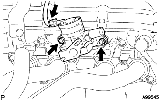
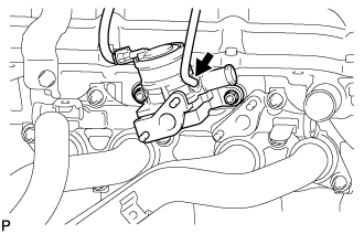
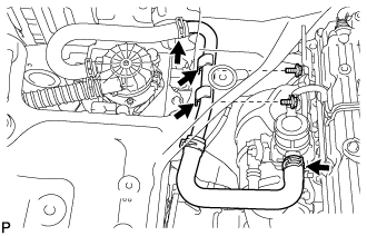
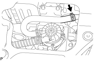
w/ Manifold Absolute Pressure Sensor: Connect the vacuum hose to the air switching valve assembly.
2.
INSTALL INTAKE PIPE NO.4
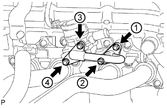
Install 2 new gaskets and the intake pipe No.4 with 4 new nuts and tighten the nuts in the order shown in the illustration. Then, tighten the nuts labeled 1 and 3 to the torque specification again.
Torque:
26 N*m{
265 kgf*cm
, 19 ft.*lbf
}
Check that the nuts are tightened to the torque specification.
NOTICE:
Tightening the nuts only once is not enough to tighten them to the torque specification.
3.
INSTALL EXHAUST MANIFOLD HEAT INSULATOR NO.1
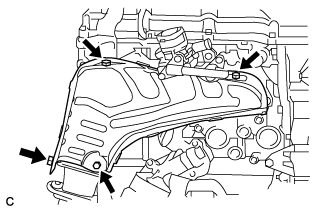
Install the heat insulator with the 4 bolts.
Torque:
12 N*m{
122 kgf*cm
, 9 ft.*lbf
}
4.
INSTALL AIR PUMP INLET PIPE
Install the air pump inlet pipe with the 2 bolts.
Torque:
12 N*m{
122 kgf*cm
, 9 ft.*lbf
}
Connect the air hose No.5 with the clip.
Connect the air hose No.6 with the clip.
5.
CONNECT AIR HOSE NO.5
Connect the air hose No.5 to the air pump inlet pipe with the clip.
6.
INSTALL BATTERY SERVICE HOLE COVER
7.
INSTALL ENGINE SERVICE HOLE SUB COVER SUB-ASSEMBLY
Install the engine service hole sub cover with the 5 bolts.
Torque:
13 N*m{
133 kgf*cm
, 10 ft.*lbf
}
8.
INSTALL FRONT DOOR SCUFF PLATE RH
9.
INSTALL FRONT SEAT ASSEMBLY RH (for Hi-back Seat Type)
Perform the same procedure as above on the opposite side. (Click here)
10.
INSTALL FRONT SEAT ASSEMBLY RH (for Low-back Seat Type)
Perform the same procedure as above on the opposite side. (Click here)
11.
INSTALL ENGINE UNDER COVER NO.2 (w/ Engine Under Cover No.2)
Install the engine under cover No.2 together with the engine side under cover LH and engine side under cover RH (for Wide Body).