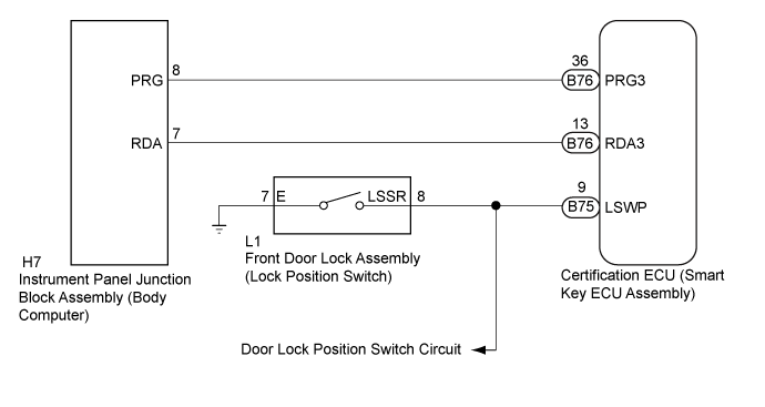
If the door lock function does not operate via smart operation from only the passenger door, but the unlock function operates normally, a normal request code is sent from the passenger door. The trouble area may be an open in the door lock position switch (LSWP) circuit.
WIRING DIAGRAM
INSPECTION PROCEDURE
NOTICE:
Check the entry lock operation at least 0.3 m (0.984 ft.) from the vehicle, as the entry lock function may not operate near the vehicle due to wave interference from the interior oscillator.
The smart entry and start system (for Entry Function) uses a multiplex communication system (LIN communication system) and the CAN communication system. Inspect the communication function by following How to Proceed with Troubleshooting (Click here). Troubleshoot the smart entry and start system (for Entry Function) after confirming that the communication systems are functioning properly.
When using the GTS with the vehicle engine switch off, connect the GTS to the vehicle and turn a courtesy light switch on and off at intervals of 1.5 seconds or less until communication between the GTS and the vehicle begins. Then select the Model Code "KEY REGIST" under manual mode and enter the following menus: Body Electrical / Entry&Start(CAN). While using the GTS, periodically turn a courtesy light switch on and off at intervals of 1.5 seconds or less to maintain communication between the GTS and the vehicle.
Check that there are no electrical key transmitter sub-assemblies in the vehicle.
Before performing the inspection, check that DTC B1242 (wireless door lock control) or B27B0 is not output.
Before replacing the certification ECU (smart key ECU assembly), refer to the smart entry and start system (for Entry Function) precaution (Click here).
After repair, confirm that no DTCs are output by performing the "DTC Output Confirmation Operation".
1. CHECK POWER DOOR LOCK CONTROL SYSTEM
When the door control switch on the power window regulator master switch assembly is operated, check that the doors unlock and lock according to the switch operation (Click here).