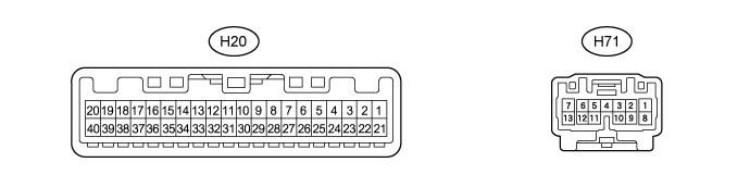
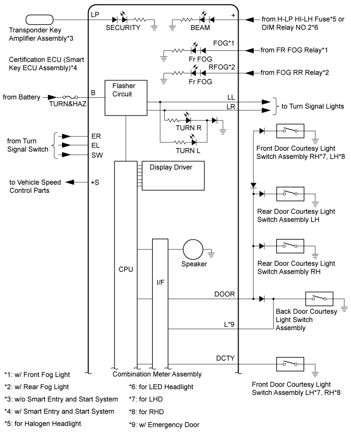
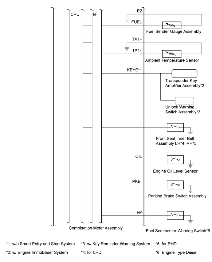
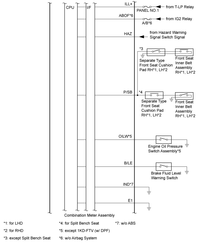
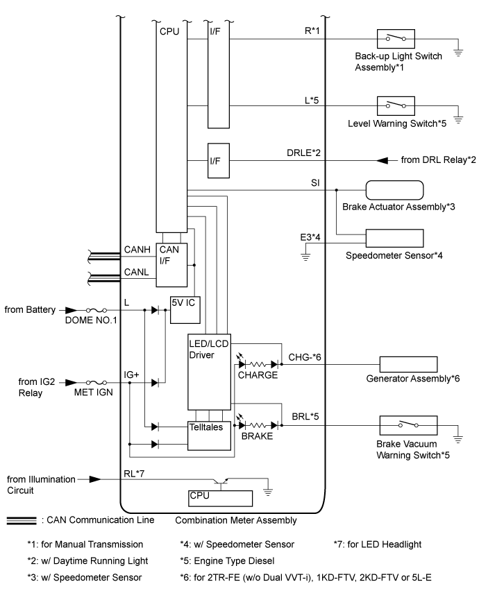
Terminal No. (Symbols)
|
Wiring Color
|
Terminal Description
|
Condition
|
Specified Condition
|
H20-1 (L) - H20-21 (E1)
|
R - W-B
|
Power source
|
Always
|
11 to 14 V
|
H20-2 (IG+) - H20-21 (E1)
|
B - W-B
|
Power source (IG)
|
Ignition switch off → ON
|
Below 1 V → 11 to 14 V
|
H20-3 (ILL+) - H20-21 (E1)
|
G - W-B
|
Illumination signal
|
Tail switch off → on
|
Below 1 V → 11 to 14 V
|
H20-4 (DCTY) - H20-21 (E1)
|
G - W-B
|
Driver side door condition signal
|
Driver side door open → closed
|
Below 1 V → 8.5 to 13.5 V
|
H20-5 (DOOR) - H20-21 (E1)
|
G - W-B
|
Except driver side door condition signal
|
Except driver side door open → closed
|
Below 1 V → 11 to 14 V
|
H20-6 (+S) - H20-21 (E1)
|
P - W-B
|
Speed signal (output)
|
Ignition switch ON, driving at approximately 20 km/h (12 mph)
|
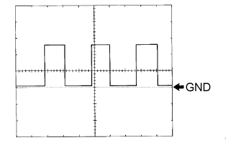
Pulse generation (See waveform 1)
|
H20-7 (SI) - H20-21 (E1)
|
P - W-B
|
Speed signal (input)
|
Ignition switch ON, driving at approximately 20 km/h (12 mph)
|
Pulse generation (See waveform 1)
|
H20-8 (OIL) - H20-21 (E1)
|
Y - W-B
|
Oil level signal
|
Ignition switch ON, OIL warning light on → off
|
8 to 13 V → Below 1 V
|
H20-9 (KEYE) - H20-21 (E1)*1
|
Y - W-B
|
Unlock warning switch signal
|
No key in ignition key cylinder → Key in ignition key cylinder
|
8.5 to 13.5 V → Below 1 V
|
H20-10 (L) - H20-21 (E1)
|
LG - W-B
|
Driver side seat belt signal
|
Ignition switch ON, driver side seat belt not unfastened → fastened
|
Below 1 V → 7.5 to 12.5 V
|
H20-11 (PKBI) - H20-21 (E1)
|
B - W-B
|
Parking brake switch signal
|
Parking brake lever pulled → released
|
Below 1 V → 9 to 13 V
|
H20-12 (HA) - H20-21 (E1)*10
|
G - W-B
|
Engine oil pressure signal
|
Ignition switch ON, SEDIMENT/FILTER indicator light on → off
|
8 to 13 V → Below 1 V
|
H20-14 (OILW) - H20-21 (E1)*2
|
W - W-B
|
Engine oil pressure signal
|
Ignition switch ON, SEDIMENT/FILTER indicator light blinking → off
|
Below 1 V ←→ 11 to 14 V → Below 1 V
|
H20-15 (CHG-) - H20-21 (E1)*8
|
B - W-B
|
Charge malfunction signal
|
Ignition switch ON, CHARGE warning light on → off
|
Below 1 V → 9 to 13 V
|
H20-17 (+) - H20-21 (E1)
|
B - W-B
|
BEAM indicator light signal
|
BEAM indicator light off → on
|
Below 1 V → 11 to 14 V
|
H20-18 (FOG) - H20-21 (E1)*3
|
Y - W-B
|
Fr FOG indicator light signal
|
Ignition switch ON, Fr FOG indicator light off → on
|
Below 1 V → 11 to 14 V
|
H20-19 (RFOG) - H20-21 (E1)*4
|
R - W-B
|
Rr FOG indicator light signal
|
Ignition switch ON, Rr FOG indicator light off → on
|
Below 1 V → 11 to 14 V
|
H20-21 (E1) - Body ground
|
W-B - Body ground
|
Ground
|
Always
|
Below 1 Ω
|
H20-22 (CANL)
|
W
|
CAN communication line
|
-
|
-
|
H20-23 (CANH)
|
B
|
CAN communication line
|
-
|
-
|
H20-24 (R) - H20-21 (E1)
|
L - W-B
|
Reverse signal
|
Ignition switch ON, shift position except R→ shift position in R
|
Below 1 V → 11 to 14 V
|
H20-25 (SW) - H20-21 (E1)
|
GR - W-B
|
Headlight dimmer switch signal (right turn or left turn position)
|
Ignition switch ON, headlight dimmer switch off → headlight dimmer switch in right turn or left turn position
|
11 to 14 V → Below 1 V
|
H20-26 (ER) - H20-21 (E1)
|
Y - W-B
|
Headlight dimmer switch signal (right turn position)
|
Ignition switch ON, headlight dimmer switch off → headlight dimmer switch in right turn position
|
11 to 14 V → Below 1 V
|
H20-27 (EL) - H20-21 (E1)
|
B - W-B
|
Headlight dimmer switch signal (left turn position)
|
Ignition switch ON, headlight dimmer switch off → headlight dimmer switch in left turn position
|
11 to 14 V → Below 1 V
|
H20-28 (HAZ) - H20-21 (E1)
|
W - W-B
|
Hazard warning switch signal
|
Hazard warning switch off →
|
11 to 14 V → Below 1 V
|
H20-29 (LP) - H20-21 (E1)
|
R - W-B
|
Security indicator light signal
|
Ignition switch ON, security indicator light blinking → off
|
Below 1 V ←→ 11 to 14 V → Below 1 V
|
H20-30 (P/SB) - H20-21 (E1)
|
W - W-B
|
Front seat belt warning light signal
|
Ignition switch ON, front passenger side seat belt unfastened and front passenger seat occupied → front passenger side seat belt fastened and front passenger seat occupied
|
11 to 14 V → Below 1 V
|
H20-31 (B/LE) - H20-21 (E1)
|
B - W-B
|
Brake fluid level warning switch signal
|
Ignition switch ON, brake fluid level warning switch on → off
|
Below 1 V → 11 to 14 V
|
H20-32 (BRL) - H20-21 (E1)*10
|
SB - W-B
|
Brake vacuum warning switch signal
|
Ignition switch ON, engine idle speed
|
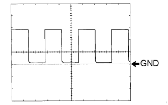
Pulse generation (See waveform 2)
|
H20-33 (FUEL) - H20-21 (E1)
|
Y - W-B
|
Fuel receiver gauge signal
|
Ignition switch ON, fuel receiver gauge F → E
|
Pulse generation (See waveform 3)
|
H20-34 (E2) - H20-21 (E1)
|
R - W-B
|
Fuel receiver gauge ground
|
Always
|
Below 1 Ω
|
H20-35 (E3) - H20-21 (E1)*5
|
G - W-B
|
Speed signal ground
|
Always
|
Below 1 Ω
|
H20-36 (TX1+) - H20-21 (E1)
|
W - W-B
|
Ambient temperature sensor ground
|
Always
|
Below 1 Ω
|
H20-37 (TX1-) - H20-21 (E1)
|
G - W-B
|
Ambient temperature sensor signal
|
Ambient temperature 25°C (77°F)
|
1.6 to 1.8 kΩ
|
H20-38 (DRLE) - H20-21 (E1)*6
|
Y - W-B
|
Daytime running light system drive output
|
Daytime running light system not operating → operating
|
11 to 14 V → Below 1 V
|
H71-1 (B) - H20-21 (E1)
|
L - W-B
|
Power source
|
Always
|
11 to 14 V
|
H71-2 (IND) - H20-21 (E1)*11
|
W-B - W-B
|
Ground
|
Always
|
Below 1 Ω
|
H71-6 (ABOF) - H20-21 (E1)*9
|
R - W-B
|
Power source (IG)
|
Ignition switch off → ON
|
Below 1 V → 11 to 14 V
|
H71-12 (RL) - H20-21 (E1)*7
|
W - W-B
|
Headlight leveling switch signal
|
Headlight dimmer switch TAIL or HEAD
|
Below 1 V
|
H71-7 (LR) - H20-21 (E1)
|
R - W-B
|
RH turn signal light signal output
|
Ignition switch ON, RH turn signal light blinking → off
|
Pulse generation → Below 1 V
|
H71-13 (LL) - H20-21 (E1)
|
L - W-B
|
LH turn signal light signal output
|
Ignition switch ON, LH turn signal light blinking → off
|
Pulse generation → Below 1 V
|