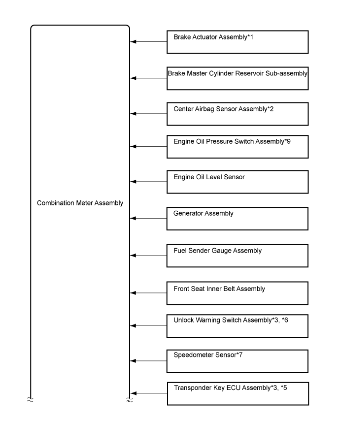
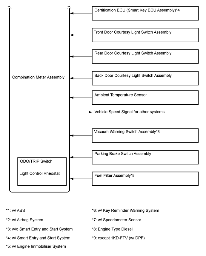
Sender
|
Receiver
|
Communication Signal
|
Communication Line
|
Combination Meter Assembly
|
- ECM
- TCM*3
- Certification ECU (Smart Key ECU Assembly)*12
- Door Control Relay (Power Slide Door ECU)*15
|
Vehicle speed signal
|
Direct Line
|
Brake Actuator Assembly*2
|
Combination Meter Assembly
|
- ABS warning light signal
- Vehicle speed signal*14
|
Direct Line
|
Brake Master Cylinder Reservoir Sub-assembly
|
Combination Meter Assembly
|
Brake fluid level warning signal
|
Direct Line
|
ECM
|
Combination Meter Assembly
|
- Tachometer signal
- Engine coolant temperature signal
- Check engine signal
- GLOW indicator light signal*3
- Shift position signal*4
- Eco driving indicator light signal*4
- Eco driving indicator zone display signal*7
- Cruise control indicator light signal*8
- SET indicator light signal*8
- Brake override system warning light signal
- Engine oil pressure signal*9
|
CAN
|
Center Airbag Sensor Assembly*5
|
Combination Meter Assembly
|
AIRBAG warning light signal
|
Direct Line
|
Engine Oil Pressure Switch Assembly*10
|
Combination Meter Assembly
|
Engine oil pressure signal
|
Direct Line
|
Engine Oil Level Sensor
|
Combination Meter Assembly
|
Engine oil level signal
|
Direct Line
|
Fuel Sender Gauge Assembly
|
Combination Meter Assembly
|
Fuel level signal
|
Direct Line
|
Front Seat Inner Belt Assembly
|
Combination Meter Assembly
|
Front seat belt condition signal
|
Direct Line
|
Each Door Courtesy Light Switch
|
Combination Meter Assembly
|
Each door condition signal
|
Direct Line
|
Speedometer Sensor*1
|
Combination Meter Assembly
|
Vehicle speed signal
|
Direct Line
|
Fuel Filter Assembly*3
|
Combination Meter Assembly
|
Fuel sedimenter signal
|
Direct Line
|
Transponder Key ECU Assembly*6, *11
|
Combination Meter Assembly
|
Security indicator light signal
|
Direct Line
|
Certification ECU (Smart Key ECU Assembly)*12
|
Combination Meter Assembly
|
Security indicator light signal
|
Direct Line
|
Generator Assembly
|
Combination Meter Assembly
|
Charge malfunction signal
|
Direct Line
|
Vacuum Warning Switch Assembly*3
|
Combination Meter Assembly
|
Vacuum warning switch signal
|
Direct Line
|
Parking Brake Switch Assembly
|
Combination Meter Assembly
|
Parking brake switch signal
|
Direct Line
|
Ambient Temperature Sensor
|
Combination Meter Assembly
|
Outside temperature signal
|
Direct Line
|
Headlight Leveling ECU Assembly*13
|
Combination Meter Assembly
|
- Headlight beam level control system indicator light signal
- LED headlight warning light signal
|
CAN
|