TERMINALS OF ECU
System information · Vehicles built from Oct 2014
| INSTRUMENT PANEL JUNCTION BLOCK (MAIN BODY ECU) [w/ Key Confine Prevention Function] |
Disconnect the 13A, 13C, 13E, 13H, 13M, 5K, and H7 instrument panel junction block connectors.
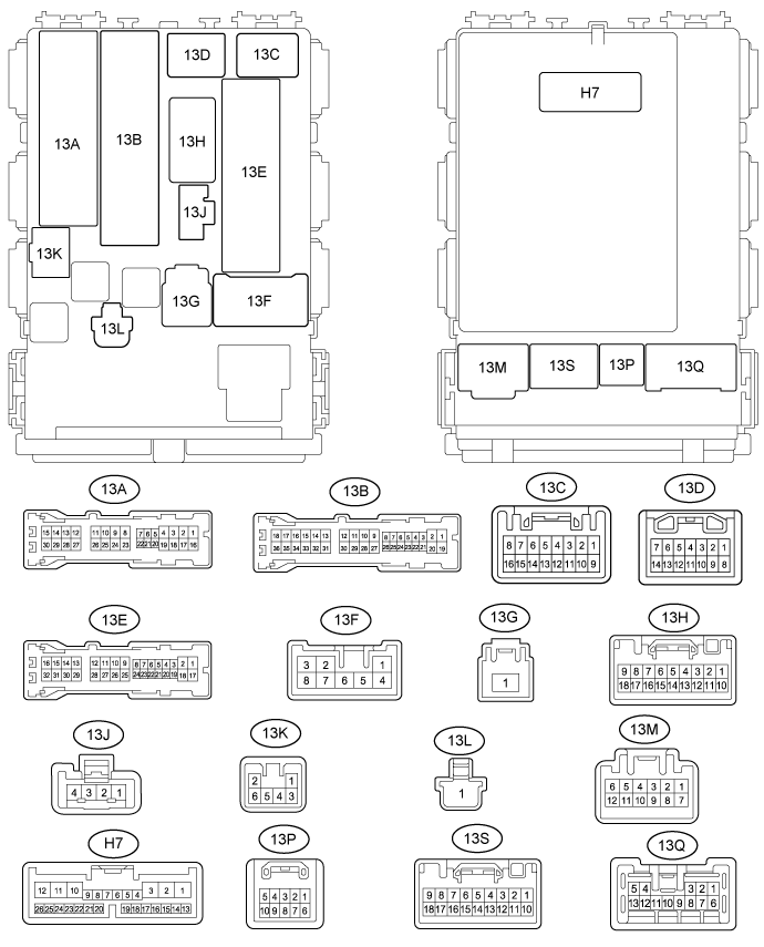

Measure the voltage and resistance between the wire harness side connectors and body ground.
If the result is not as specified, there may be a malfunction on the wire harness side.Terminal No.
(Symbol)
Wiring Color
Terminal Description
Condition
Specified Condition
13A-18 (RRCY) - 13M-7 (GND)*1
W - W-B
Rear door courtesy switch RH signal
Rear door RH open
Below 1 V
13A-18 (RRCY) - 13M-7 (GND)*1
W - W-B
Rear door courtesy switch RH signal
Rear door RH closed
11 to 14 V
13A-24 (RRCY) - 13M-7 (GND)
W - W-B*3
Back door courtesy switch signal
Back door open
Below 1 V
13A-24 (RRCY) - 13M-7 (GND)
W - W-B*3
Back door courtesy switch signal
Back door closed
11 to 14 V
13A-30 (RRCY) - 13M-7 (GND)*1
W - W-B
Rear door courtesy switch LH signal
Rear door LH open
Below 1 V
13A-30 (RRCY) - 13M-7 (GND)*1
W - W-B
Rear door courtesy switch LH signal
Rear door LH closed
11 to 14 V
13F-1 (BECU) - Body ground
L - Body ground
Battery power supply
Always
11 to 14 V
13E-9 (DIM) - 13M-7 (GND)
GR - W-B
Headlight dimmer switch signal
Headlight dimmer switch in tail position
Below 1 V
13E-9 (DIM) - 13M-7 (GND)
GR - W-B
Headlight dimmer switch signal
Headlight dimmer switch not in high or high flash position
11 to 14 V
13E-8 (DOMR) - 13M-7 (GND)*2
W - W-B
Battery save system (interior light auto cut function) signal
Battery save system (interior light auto cut function) not operating
Below 1 V
13E-8 (DOMR) - 13M-7 (GND)*2
W - W-B
Battery save system (interior light auto cut function) signal
Battery save system (interior light auto cut function) operating
11 to 14 V
13E-10 (PCTY) - 13M-7 (GND)
R - W-B
Front passenger side door courtesy switch signal
Front passenger side door open
Below 1 V
13E-10 (PCTY) - 13M-7 (GND)
R - W-B
Front passenger side door courtesy switch signal
Front passenger side door closed
11 to 14 V
13E-11 (DCTY) - 13M-7 (GND)
G - W-B
Driver side door courtesy switch signal
Driver side door open
Below 1 V
13E-11 (DCTY) - 13M-7 (GND)
G - W-B
Driver side door courtesy switch signal
Driver side door closed
11 to 14 V
13M-7 (GND) - Body ground
W-B - Body ground
Ground
Always
Below 1 Ω
13E-20 (HRLY) - 13M-7 (GND)
R - W-B
HEAD relay drive signal
Headlight dimmer switch off
11 to 14 V
13E-20 (HRLY) - 13M-7 (GND)
R - W-B
HEAD relay drive signal
Headlight dimmer switch on
Below 1 V
13H-3 (TRLY) - 13M-7 (GND)
G - W-B
Headlight dimmer switch signal
Headlight dimmer switch off
11 to 14 V
13H-3 (TRLY) - 13M-7 (GND)
G - W-B
Headlight dimmer switch signal
Headlight dimmer switch TAIL
Below 1 V
13K-2 (ILE) - 13M-7 (GND)
LG - W-B*3
Y - W-B*4
Map light light signal
Map light off using illuminated entry system
11 to 14 V
13K-2 (ILE) - 13M-7 (GND)
LG - W-B*3
Y - W-B*4
Map light light signal
Map light on using illuminated entry system
Below 1 V
13H-5 (ILE) - 13M-7 (GND)*5
L - W-B
Ignition key cylinder light signal*9
Transponder key light signal*10
Ignition key cylinder light off using illuminated entry system*9
Transponder key light off using illuminated entry system*10
11 to 14 V
13H-5 (ILE) - 13M-7 (GND)*5
L - W-B
Ignition key cylinder light signal*9
Transponder key light signal*10
Ignition key cylinder light on using illuminated entry system*9
Transponder key light on using illuminated entry system*10
Below 1 V
H7-10 (CLTB) - 13M-7 (GND)*6
P - W-B
Automatic light control sensor signal
Always
11 to 14 V
H7-11 (CLTS) - 13M-7 (GND)*6
B - W-B
Automatic light control sensor signal
Ignition switch off
Below 1 V
H7-11 (CLTS) - 13M-7 (GND)*1
B - W-B
Automatic light control sensor signal
Ignition switch ON
Headlight dimmer switch AUTO
Pulse generation
(See waveform 1)
H7-12 (CLTE) - 13M-7 (GND)*6
W - W-B
Ground
Always
Driver side door unlock detection switch signal
H7-13 (A) - 13M-7 (GND)*6
BE - W-B
Headlight dimmer switch signal
Headlight dimmer switch off
11 to 14 V
H7-13 (A) - 13M-7 (GND)*6
BE - W-B
Headlight dimmer switch signal
Headlight dimmer switch AUTO
Below 1 V
H7-15 (HEAD) - 13M-7 (GND)
R - W-B
Headlight dimmer switch signal
Headlight dimmer switch off
11 to 14 V
H7-15 (HEAD) - 13M-7 (GND)
R - W-B
Headlight dimmer switch signal
Headlight dimmer switch HEAD
Below 1 V
H7-17 (FFOG) - 13M-7 (GND)*7
P - W-B
Front fog light switch input
Front fog light switch off
11 to 14 V
H7-17 (FFOG) - 13M-7 (GND)*7
P - W-B
Front fog light switch input
Front fog light switch on
Below 1 V
H7-16 (RFOG) - 13M-7 (GND)*8
R - W-B
Rear fog light switch input
Rear fog light switch off
11 to 14 V
H7-16 (RFOG) - 13M-7 (GND)*8
R - W-B
Rear fog light switch input
Rear fog light switch on
Below 1 V
H7-18 (HF) - 13M-7 (GND)
B - W-B
Headlight dimmer switch high flash signal input
Headlight dimmer switch not in high flash position
11 to 14 V
H7-18 (HF) - 13M-7 (GND)
B - W-B
Headlight dimmer switch high flash signal input
Headlight dimmer switch in high flash position
Below 1 V
H7-19 (HU) - 13M-7 (GND)
GR - W-B
Headlight dimmer switch high signal input
Headlight dimmer switch in low position
11 to 14 V
H7-19 (HU) - 13M-7 (GND)
GR - W-B
Headlight dimmer switch high signal input
Headlight dimmer switch in high position
Below 1 V
13C-8 (FFGO) - 13M-7 (GND)*7
GR - W-B
Front fog light signal output
Front fog light switch off
11 to 14 V
13C-8 (FFGO) - 13M-7 (GND)*7
GR - W-B
Front fog light signal output
Headlight dimmer switch in tail position and front fog light switch on
Below 1 V
13C-16 (RFGO) - 13M-7 (GND)*8
Y - W-B
Rear fog light signal output
Rear fog light switch off
11 to 14 V
13C-16 (RFGO) - 13M-7 (GND)*8
Y - W-B
Rear fog light signal output
Headlight dimmer switch in tail position and rear fog light switch on
Below 1 V
*1: for 5-Door
*2: w/ Key Confine Prevention Function
*3: w/ Personal Light Assembly
*4: w/o Personal Light Assembly
*5: w/o Smart Entry and Start System
*6: w/ Automatic Light Control System
*7: w/ Front Fog Light
*8: w/ Rear Fog Light
*9: w/o Engine Immobiliser System
*10: w/ Engine Immobiliser System
Waveform 1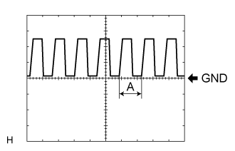
Item
Description
Terminal
H7-11 (CLTS) - 13M-7 (GND)
Gauge
5 V/DIV, 5 ms/DIV
Condition
Ignition switch ON, Headlight dimmer switch AUTO
- HINT:
- If the ambient light becomes brighter, width A becomes narrower.
| HEADLIGHT LEVELING ECU ASSEMBLY (for LED Headlight) |
Disconnect the A39 headlight leveling ECU connector.

Measure the voltage and resistance between the wire harness side connectors and body ground.
If the result is not as specified, there may be a malfunction on the wire harness side.Terminal No.
(Symbol)
Wiring Color
Terminal Description
Condition
Specified Condition
A39-1 (IG) - A39-9 (E1)
B - W-B
Ignition power supply
Ignition switch off
Below 1 V
A39-1 (IG) - A39-9 (E1)
B - W-B
Ignition power supply
Ignition switch ON
11 to 14 V
A39-2 (RLEW) - A39-9 (E1)
G - W-B
LED headlight signal input
Headlight dimmer switch off
Below 1 V
A39-2 (RLEW) - A39-9 (E1)
G - W-B
LED headlight signal input
Headlight dimmer switch in head position
Pulse generation
A39-3 (LLEW) - A39-9 (E1)
L - W-B
LED headlight signal input
Headlight dimmer switch off
Below 1 V
A39-3 (LLEW) - A39-9 (E1)
L - W-B
LED headlight signal input
Headlight dimmer switch in head position
Pulse generation
A39-4 (HDLP) - A39-9 (E1)
R - W-B
Low beam headlight signal input
Low beam headlights on
Below 1 V
A39-4 (HDLP) - A39-9 (E1)
R - W-B
Low beam headlight signal input
Low beam headlights off
11 to 14 V
A39-9 (E1) - Body ground
W-B - Body ground
Ground
Always
Below 1 Ω
A39-10 (RH+) - A39-9 (E1)
R - W-B
Headlight leveling motor RH power supply
Ignition switch off
Below 1 V
A39-10 (RH+) - A39-9 (E1)
R - W-B
Headlight leveling motor RH power supply
Ignition switch ON
11 to 14 V
A39-11 (LH+) - A39-9 (E1)
W - W-B
Headlight leveling motor LH power supply
Ignition switch off
Below 1 V
A39-11 (LH+) - A39-9 (E1)
W - W-B
Headlight leveling motor LH power supply
Ignition switch ON
11 to 14 V
A39-12 (SBR) - A39-21 (SGR)
BE - G
Rear height control sensor power supply
Ignition switch off
Below 1 V
A39-12 (SBR) - A39-21 (SGR)
BE - G
Rear height control sensor power supply
Ignition switch ON
4.75 to 5.25 V
A39-17 (RHT) - A39-9 (E1)
V - W-B
Headlight leveling motor RH operation signal input
With low beam headlights on, vehicle height not changed
Below 1 V
A39-17 (RHT) - A39-9 (E1)
V - W-B
Headlight leveling motor RH operation signal input
With low beam headlights on, vehicle height changed and maintained for more than 3 seconds
1 to 14.4 V
A39-18 (LHT) - A39-9 (E1)
Y - W-B
Headlight leveling motor LH operation signal input
With low beam headlights on, vehicle height not changed
Below 1 V
A39-18 (LHT) - A39-9 (E1)
Y - W-B
Headlight leveling motor LH operation signal input
With low beam headlights on, vehicle height changed and maintained for more than 3 seconds
1 to 14.4 V
A39-19 (SHRL) - A39-21 (SGR)
L - G
Rear height control sensor signal input
Ignition switch off
Below 1 V
A39-19 (SHRL) - A39-21 (SGR)
L - G
Rear height control sensor signal input
Ignition switch ON
0.5 to 4.5 V
A39-21 (SGR) - A39-9 (E1)
G - W-B
Rear height control sensor ground
Always
Below 1 Ω
A39-23 (RH-) - A31-9 (E1)
L - W-B
Headlight leveling motor RH ground
Always
Below 1 Ω
A39-24 (LH-) - A39-9 (E1)
LG - W-B
Headlight leveling motor LH ground
Always
Below 1 Ω
| COMBINATION METER ASSEMBLY |
Disconnect the H20 and H71 combination meter connectors.
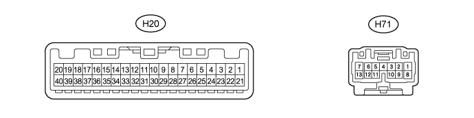
Measure the voltage and resistance between the wire harness side connectors and body ground.
If the result is not as specified, there may be a malfunction on the wire harness side.Terminal No.
(Symbol)
Wiring Color
Terminal Description
Condition
Specified Condition
H20-2 (IG+) - Body ground
B - Body ground
Ignition power supply
Ignition switch off
Below 1 V
H20-2 (IG+) - Body ground
B - Body ground
Ignition power supply
Ignition switch ON
11 to 14 V
H20-21 (E1) - Body ground
W-B - Body ground
Ground
Always
Below 1 Ω
H20-25 (SW) - Body ground
GR - Body ground
Turn signal switch (right turn or left turn position) signal input
Ignition switch ON
Turn signal switch off
11 to 14 V
H20-25 (SW) - Body ground
GR - Body ground
Turn signal switch (right turn or left turn position) signal input
Ignition switch ON
Turn signal switch in right turn or left turn position
Below 1 V
H20-26 (ER) - Body ground
Y - Body ground
Turn signal switch (right turn position) signal input
Ignition switch ON
Turn signal switch off
11 to 14 V
H20-26 (ER) - Body ground
Y - Body ground
Turn signal switch (right turn position) signal input
Ignition switch ON
Turn signal switch in right turn position
Below 1 V
H20-27 (EL) - Body ground
B - Body ground
Turn signal switch (left turn position) signal input
Ignition switch ON
Turn signal switch off
11 to 14 V
H20-27 (EL) - Body ground
B - Body ground
Turn signal switch (left turn position) signal input
Ignition switch ON
Turn signal switch in left turn position
Below 1 V
H20-28 (HAZ) - Body ground
W - Body ground
Hazard warning switch signal
Hazard warning switch off
11 to 14 V
H20-28 (HAZ) - Body ground
W - Body ground
Hazard warning switch signal
Hazard warning switch on
Below 1 V
H20-38 (DRLE) - Body ground*
Y - Body ground
Daytime running light system drive output
Daytime running light system not operating
11 to 14 V
H20-38 (DRLE) - Body ground*
Y - Body ground
Daytime running light system drive output
Daytime running light system operating
Below 1 V
H71-1 (B) - Body ground
L - Body ground
Battery power supply
Always
11 to 14 V
H71-7 (LR) - Body ground
R - Body ground
RH turn signal light signal output
Ignition switch ON
RH turn signal light off
Below 1 V
H71-7 (LR) - Body ground
R - Body ground
RH turn signal light signal output
Ignition switch ON
RH turn signal light blinking
Below 1 V ←→ 11 to 14 V
H71-13 (LL) - Body ground
L - Body ground
LH turn signal light signal output
Ignition switch ON
LH turn signal light off
Below 1 V
H71-13 (LL) - Body ground
L - Body ground
LH turn signal light signal output
Ignition switch ON
LH turn signal light blinking
Below 1 V ←→ 11 to 14 V
*: w/ Daytime Running Light
| CERTIFICATION ECU (SMART KEY ECU ASSEMBLY) [w/ Smart Entry and Start System] |
Disconnect the B75 certification ECU connector.
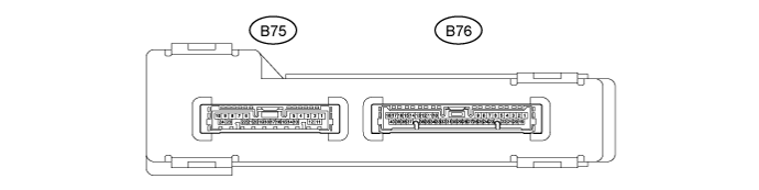
Measure the voltage and resistance between the wire harness side connectors and body ground.
If the result is not as specified, there may be a malfunction on the wire harness side.Terminal No.
(Symbol)
Wiring Color
Terminal Description
Condition
Specified Condition
B75-1 (+B) - Body ground
L - Body ground
Battery power supply
Always
11 to 14 V
B75-10 (E) - Body ground
W-B - Body ground
Ground
Always
Below 1 Ω
B75-19 (SWIL) - B75-24 (AGND)
P - V
Engine switch illumination operation signal
Engine switch illumination on
11 to 14 V
B75-19 (SWIL) - B75-24 (AGND)
P - V
Engine switch illumination operation signal
Engine switch illumination off
Below 1 V