TERMINALS OF ECU
System information · Vehicles built Oct 2014 – Dec 2016
Versions by build date: Oct 2014 – Dec 2016 from Jan 2017
| INSTRUMENT PANEL JUNCTION BLOCK ASSEMBLY (BODY ECU) |
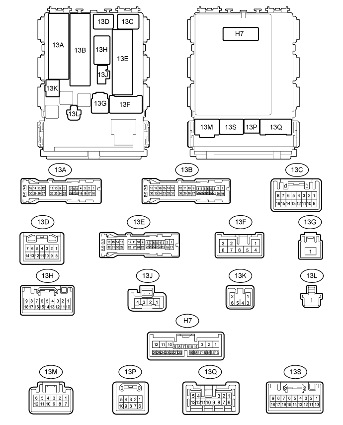

Disconnect the 13B, 13C, 13E, 13G and H7 instrument panel junction block assembly (body ECU) connectors.
Measure the resistance and voltage according to the value(s) in the table below.
Terminal No. (Symbol)
Wiring Color
Terminal Description
Condition
Specified Condition
13B-3 (L2) - Body ground
W - Body ground
Door lock key switch signal
Front door lock key switch off → On (unlock)
10 kΩ or higher → Below 1 Ω
13B-4 (UL2) - Body ground
Y - Body ground
Door lock key switch signal
Front RH door lock key switch off → On (lock)
10 kΩ or higher → Below 1 Ω
13B-5 (UL1) - Body ground
Y - Body ground
Door lock manual switch signal
Driver side door control switch off → On (unlock)
10 kΩ or higher → Below 1 Ω
13B-6 (L1) - Body ground
W - Body ground
Door lock manual switch signal
Driver side door control switch off → On (lock)
10 kΩ or higher → Below 1 Ω
13B-21 (L2) - Body ground
W - Body ground
Door lock key switch signal
Front LH door lock key switch off → On (unlock)
10 kΩ or higher → Below 1 Ω
13B-22 (UL2) - Body ground
Y - Body ground
Door lock key switch signal
Front LH door lock key switch off → On (lock)
10 kΩ or higher → Below 1 Ω
13C-4 (IG) - Body ground
B - Body ground
Ignition power supply
Ignition switch off → ON
Below 1 V → 11 to 14 V
13E-12 (GND) - Body ground
W-B - Body ground
Ground
Always
Below 1 Ω
13G-1 (BECU) - Body ground
B-G - Body ground
Battery power supply
Always
11 to 14 V
H7-4 (LSWD) - Body ground
W - Body ground
Front door lock detection switch RH signal
Front door lock RH lock → Unlock
10 kΩ or higher → Below 1 Ω
Reconnect the 13B, 13C, 13E, 13G and H7 instrument panel junction block assembly (body ECU) connectors.
Measure the voltage according to the value(s) in the table below.
Terminal No. (Symbols)
Wiring Color
Terminal Description
Condition
Specified Condition
13A-10 (ACT+) - Body ground
L - Body ground
Back door lock motor drive signal
Back door control switch off → On (lock)
Below 1 V → 11 to 14 V → Below 1 V
13A-18 (RRCY) - Body ground
W - Body ground
Rear door courtesy light switch assembly RH signal
Rear door RH door closed → Open
- 11 to 14 V* → Below 1 V
- Pulse generation* → Below 1 V
13A-24 (RRCY) - Body ground
W - Body ground
Back door courtesy light switch signal
Back door door closed → Open
- 11 to 14 V* → Below 1 V
- Pulse generation* → Below 1 V
13A-29 (ACT-) - Body ground
R - Body ground
Back door lock motor drive signal
Back door control switch off → On (unlock)
Below 1 V → 11 to 14 V → Below 1 V
13A-30 (RRCY) - Body ground
W - Body ground
Rear door courtesy light switch assembly LH signal
Rear door LH door closed → Open
- 11 to 14 V* → Below 1 V
- Pulse generation* → Below 1 V
13B-17 (ACT+) - Body ground
L - Body ground
Front door lock motor LH/RH drive signal
Door control switch off → On (lock)
Below 1 V → 11 to 14 V → Below 1 V
13B-35 (ACT-) - Body ground
R - Body ground
Front door lock motor LH/RH drive signal
Door control switch off → On (unlock)
Below 1 V → 11 to 14 V → Below 1 V
13E-10 (PCTY) - Body ground
R - Body ground
Front door courtesy light switch assembly (for Front Passenger Side) signal
Front passenger side door closed → Open
- 11 to 14 V* → Below 1 V
- Pulse generation* → Below 1 V
13E-11 (DCTY) - Body ground
G - Body ground
Front door courtesy light switch assembly (for Driver Side) signal
Driver side door closed → Open
- 11 to 14 V* → Below 1 V
- Pulse generation* → Below 1 V
13E-26 (ACT+) - Body ground
L - Body ground
Slide door lock motor LH/RH drive signal
Slide door lock control switch off → On (lock)
Below 1 V → 11 to 14 V → Below 1 V
13E-27 (ACT-) - Body ground
R - Body ground
Slide door lock motor LH/RH drive signal
Slide door lock control switch off → On (unlock)
Below 1 V → 11 to 14 V → Below 1 V
H7-6 (HAZ) - Body ground
W - Body ground
Hazard warning light signal
Hazard warning signal switch off → On
11 to 14 V → Below 1 V
H7-7 (RDA) - Body ground
W - Body ground
Door control receiver input
No key in ignition key cylinder, all doors closed and transmitter switch off → On
Pulse generation
H7-8 (PRG) - Body ground
B - Body ground
Door control receiver output)
Key in ignition key cylinder → No key in ignition key cylinder
Pulse generation
- *: The specified value changes depending on vehicle conditions.
- 11 to 14 V* → Below 1 V