ON-VEHICLE INSPECTION
Inspection · Vehicles built from Oct 2014
| INSPECT ENGINE COOLANT |

Remove the radiator cap.
- CAUTION:
- Do not remove the radiator cap while the engine and radiator are still hot. Pressurized, hot engine coolant and steam may be released and cause serious burns.
Check if there is any excessive deposits of rust or scale around the radiator cap and radiator filler hole. The coolant should be free from oil.
- HINT:
- If excessively dirty, clean the coolant passage and replace the coolant.
Install the radiator cap.
| INSPECT ENGINE OIL |
Warm up the engine, stop the engine and wait for 5 minutes. The oil level should be between the low and full level marks of the dipstick.
If low, check for leakage and add oil up to the full level mark.- NOTICE:
- Do not fill the engine oil above the full level mark.
| INSPECT BATTERY |
- CAUTION:
- If the battery is weak or if the engine is difficult to start, perform the following procedures.
Check the battery for damage and deformation. If severe damage, deformation, or leakage is found, replace the battery.
Check the electrolyte level of each cell.
For maintenance-free batteries:
- If the electrolyte level is below the lower line, replace the battery.
- If the electrolyte level is above the lower line, check the battery voltage when cranking the engine.
- If the voltage is less than 9.6 V, recharge or replace the battery.
- HINT:
- Before checking battery voltage, turn off all the electrical systems (headlights, blower motor, rear defogger, etc.).
- If the electrolyte level is below the lower line, replace the battery.
For non-maintenance-free batteries:
- If the electrolyte level is below the lower line, add distilled water to each cell. Then, recharge the battery and check the electrolyte gravity.
- Standard gravity:
- 1.25 to 1.29 at 20°C (68°F)
- HINT:
- Before checking battery voltage, turn off all the electrical systems (headlights, blower motor, rear defogger, etc.).
- If the electrolyte level is below the lower line, add distilled water to each cell. Then, recharge the battery and check the electrolyte gravity.
| INSPECT AIR CLEANER FILTER ELEMENT SUB-ASSEMBLY |
Remove the air cleaner filter element from the air cleaner case.
Visually check that there no dirt, clog, and damage to the air cleaner filter element.
- HINT:
- If there is any dirt or clog on the air cleaner filter element, clean it with compressed air.
- If any dirt or clog remains even after cleaning the air cleaner filter element with compressed air, replace it.
- If there is any dirt or clog on the air cleaner filter element, clean it with compressed air.
| CHECK IDLE SPEED |
- NOTICE:
- This checking procedure should be done under the following condition.
- HINT:
- Regarding the details about the intelligent tester, refer to its operator's manual.
- If the intelligent tester is not available, a tachometer's tester probe can substitute for it.
- Regarding the details about the intelligent tester, refer to its operator's manual.
Connect the intelligent tester to the DLC3.
If the tester is not available, connect a tester probe of a tachometer to terminal 9 (TAC) of the DLC3 with SST.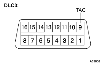

- SST
- 09843-18030
Start the engine and check the idle speed.
- Idle speed:
- 700 to 800 rpm
- HINT:
- If the idle speed is not as specified, check by troubleshooting in the diagnostics section.
In case of the tester probe of the tachometer is connected to the DLC3, disconnect the tester probe from terminal 9 of the DLC3 with SST.
Disconnect the intelligent tester from the DLC3.
| INSPECT MAXIMUM ENGINE SPEED |
- NOTICE:
- This checking procedure should be done under the following condition.
- HINT:
- Regarding the details about the intelligent tester, refer to its operator's manual.
- If the intelligent tester is not available, a tachometer's tester probe can substitute for it.
- Regarding the details about the intelligent tester, refer to its operator's manual.
Connect the intelligent tester to the DLC3.
If the tester is not available, connect a tester probe of a tachometer to terminal 9 (TAC) of the DLC3 with SST.
- SST
- 09843-18030
Start the engine.
Depress the accelerator pedal all the way to the limit.
Check the maximum speed.
- Maximum speed:
- 4500 to 4700 rpm
- HINT:
- If the maximum speed is not as specified, check by troubleshooting in the diagnostics section.
In case of the tester probe of the tachometer is connected to the DLC3, disconnect the tester probe from terminal 9 of the DLC3 with SST.
Disconnect the intelligent tester from the DLC3.
| INSPECT COMPRESSION PRESSURE |
- HINT:
- Measure the compression pressure if the engine power is insufficient, oil is consumed excessively and/or fuel economy is poor.
Remove all the 4 glow plug assemblies.
Disconnect all the connectors from the 4 injectors.
Evacuate extraneous stuff such as soot in the cylinder by turning the starter.
Set SST (attachment) into the glow plug hole.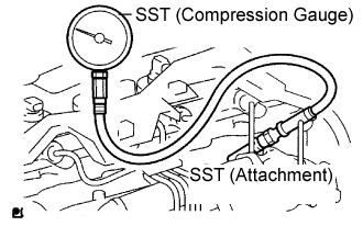
- SST
- 09992-00025
(09992-00121, 09992-00211)
- Torque:
- 13 N*m{ 133 kgf*cm , 10 ft.*lbf }
Measure the compression pressure while cranking the engine.
- HINT:
- Always use a full-charged battery to obtain engine revolution of 250 rpm or more.
Repeat steps (d) and (e) for each cylinder.
- NOTICE:
- This measurement must be done as quickly as possible.
- Compression pressure:
- 2,700 kPa (27.5 kgf/cm2, 391 psi) or more
- Minimum pressure:
- 2,200 kPa (22.5 kgf/cm2, 320 psi) or more
- Difference between each cylinder:
- 500 kPa (5.0 kgf/cm2, 71 psi) or less
- HINT:
- If the compression in one or more cylinders is low, supply a bit of engine oil into glow plug hole. Then, repeat the above mentioned steps, (d) and (e), for the low-compression cylinder.
- If poor compression becomes good by supplying the engine oil, the piston rings and/or cylinder bore may have worn or damaged.
- If pressure stays low, it is possible that a valve is sticking or seating improperly, or pressure may be leaked through the gasket.
- If the compression in one or more cylinders is low, supply a bit of engine oil into glow plug hole. Then, repeat the above mentioned steps, (d) and (e), for the low-compression cylinder.
Remove the SST (attachment and compression gauge).
Connect all the connectors to the 4 injectors.
Install all the 4 glow plug assemblies.