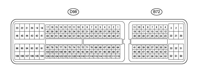
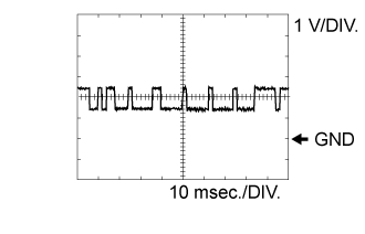
Terminal No. (Symbol)
|
Wiring Color
|
Terminal Description
|
Condition
|
Specified Condition
|
B72-2 (BATT) - D98-109 (E1)
|
W - W-B
|
Battery (for measuring the battery voltage and for the ECM memory)
|
Always
|
11 to 14 V
|
B72-25 (IGSW) - D98-109 (E1)
|
B - W-B
|
Ignition switch
|
Ignition switch ON
|
11 to 14 V
|
B72-1 (+B) - D98-109 (E1)
|
L - W-B
|
Power source of ECM
|
Ignition switch ON
|
11 to 14 V
|
B72-20 (+B2) - D98-109 (E1)
|
L - W-B
|
Power source of ECM
|
Ignition switch ON
|
11 to 14 V
|
B72-45 (MREL) - D98-109 (E1)
|
G - W-B
|
EFI MAIN relay
|
Ignition switch ON
|
11 to 14 V
|
10 seconds elapsed after ignition switch off
|
0 to 1.5 V
|
B72-55 (VCPA) - B72-56 (EPA)
|
W - G
|
Power source of accelerator pedal position sensor (for VPA)
|
Ignition switch ON
|
4.5 to 5.5 V
|
B72-57 (VCP2) - B72-58 (EPA2)
|
R - GR
|
Power source of accelerator pedal position sensor (for VPA2)
|
Ignition switch ON
|
4.5 to 5.5 V
|
B72-53 (VPA) - B72-56 (EPA)
|
L - G
|
Accelerator pedal position sensor (for engine control)
|
Ignition switch ON, accelerator pedal fully released
|
0.5 to 1.1 V
|
Ignition switch ON, accelerator pedal fully depressed
|
3.0 to 4.6 V
|
B72-54 (VPA2) - B72-58 (EPA2)
|
B - GR
|
Accelerator pedal position sensor (for sensor malfunction detection)
|
Ignition switch ON, accelerator pedal fully released
|
0.9 to 2.3 V
|
Ignition switch ON, accelerator pedal fully depressed
|
3.4 to 5.0 V
|
D98-65 (VG) - D98-64 (EVG)
|
B-L - GR
|
Mass air flow meter
|
Idling
|
Pulse generation
|
D98-110 (THA) - D98-87 (ETHA)
|
R - Y
|
Intake air temperature sensor (built into mass air flow meter)
|
Idling, intake air temperature at 20°C (68°F)
|
0.5 to 3.4 V
|
D98-113 (THIA) - D98-90 (ETHI)
|
R - Y
|
Intake air temperature sensor
|
Idling, intake air temperature at 0 to 80°C (32 to 176°F)
|
0.5 to 3.4 V
|
D98-111 (THW) - D98-88 (ETHW)
|
R - Y
|
Engine coolant temperature sensor
|
Idling, engine coolant temperature at 80°C (176°F)
|
0.2 to 1.0 V
|
D98-112 (THF) - D98-89 (ETHF)
|
R - B
|
Fuel temperature sensor
|
Ignition switch ON
|
0.5 to 3.4 V
|
B72-43 (STA) - D98-109 (E1)
|
R - W-B
|
Starter signal
|
Cranking
|
6.0 V or higher
|
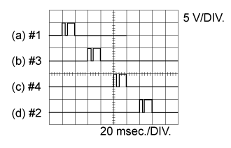
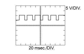
D98-50 (#1) - D98-109 (E1)
|
G - W-B
|
Injector assembly
|
Idling
|
Pulse generation
(See waveform 2)
|
D98-49 (#2) - D98-109 (E1)
|
GR - W-B
|
D98-48 (#3) - D98-109 (E1)
|
Y - W-B
|
D98-47 (#4) - D98-109 (E1)
|
B - W-B
|
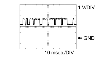
D98-80 (G+) - D98-79 (G-)
|
R - G
|
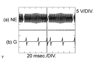
Camshaft position sensor
|
Idling
|
Pulse generation
(See waveform 4)
|
D98-103 (NE+) - D98-102 (NE-)
|
B - W
|
Crankshaft position sensor
|
Idling
|
Pulse generation
(See waveform 4)
|
B72-35 (STP) - D98-109 (E1)
|
Y - W-B
|
Stop light switch assembly
|
Ignition switch ON, brake pedal depressed
|
7.5 to 14 V
|
Ignition switch ON, brake pedal released
|
0 to 1.5 V
|
B72-34 (ST1-) - D98-109 (E1)
|
R - W-B
|
Stop light switch assembly
(opposite to STP)
|
Ignition switch ON, brake pedal depressed
|
0 to 1.5 V
|
Ignition switch ON, brake pedal released
|
7.5 to 14 V
|
D98-73 (CLSW)*1 - D98-109 (E1)
|
R - W-B
|
Clutch switch assembly
|
Ignition switch ON, clutch pedal released
|
8.5 to 14 V
|
B72-26 (TC) - D98-109 (E1)
|
G - W-B
|
Terminal TC of DLC3
|
Ignition switch ON
|
11 to 14 V
|
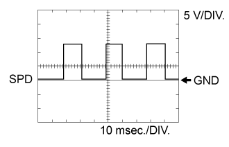
B72-14 (SPD) - D98-109 (E1)
|
P - W-B
|
Speed signal from combination meter assembly
|
Ignition switch ON, slowly wheel rotated
|
Pulse generation
(See waveform 8)
|
D98-93 (VCPM) - D98-72 (EPIM)
|
L - G
|
Power source of manifold absolute pressure sensor
|
Ignition switch ON
|
4.5 to 5.5 V
|
D98-117 (PIM) - D98-72 (EPIM)
|
P - G
|
Manifold absolute pressure sensor
|
Negative pressure of 40 kPa (300 mmHg, 11.8 in.Hg) applied
|
0.1 to 0.7 V
|
Same as atmospheric pressure
|
0.8 to 1.5 V
|
Positive pressure of 170 kPa (1275 mmHg, 50.2 in.Hg) applied
|
1.6 to 2.3 V
|
B72-44 (IREL) - D98-109 (E1)
|
R - W-B
|
EDU relay
|
Ignition switch ON
|
0 to 1.5 V
|
B72-13 (TACH) - D98-109 (E1)
|
B - W-B
|
Engine speed
|
Idling
|
Pulse generation
|
D98-69 (VCM) - D98-91 (E2M)
|
L-R - Y
|
Power source of fuel pressure sensor (for PCR1)
|
Ignition switch ON
|
4.5 to 5.5 V
|
D98-68 (VCS) - D98-67 (E2S)
|
G-B - G
|
Power source of fuel pressure sensor (for PCR2)
|
Ignition switch ON
|
4.5 to 5.5 V
|
D98-66 (PCR1) - D98-91 (E2M)
|
P - Y
|
Fuel pressure sensor (main)
|
Idling
|
1.8 to 2.1 V
|
D98-114 (PCR2) - D98-67 (E2S)
|
G-R - G
|
Fuel pressure sensor (sub)
|
Idling
|
1.2 to 1.5 V
|
D98-54 (ALT) - D98-109 (E1)
|
W - W-B
|
Generator assembly (Alternator) duty ratio
|
Idling
|
Pulse generation
|
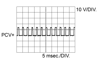
D98-41 (PCV+) - D98-81 (PCV-)
|
P - Y
|
Suction control valve
|
Idling
|
Pulse generation
(See waveform 1)
|
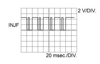
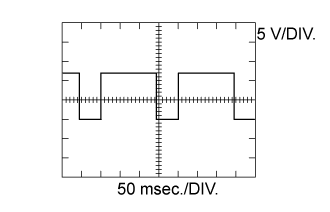
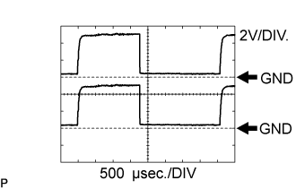
D98-51 (INJF) - D98-109 (E1)
|
LG - W-B
|
Injector driver
|
Idling
|
Pulse generation
(See waveform 3)
|
D98-52 (PRD) - D98-109 (E1)
|
V - W-B
|
Pressure discharge valve drive signal
|
Engine warmed up, engine racing
|
Pulse generation
|
D98-86 (VNM+) - D98-109 (E1)
|
R - W-B
|
DC motor (turbocharger sub-assembly)
|
Idling
|
Pulse generation
(See waveform 5)
|
D98-85 (VNM-) - D98-109 (E1)
|
G - W-B
|
DC motor (turbocharger sub-assembly)
|
Idling
|
Pulse generation
(See waveform 6)
|
D98-94 (VNVC) - D98-95 (VNE2)
|
G - R
|
Power source of nozzle vane position sensor
|
Ignition switch ON
|
4.5 to 5.5 V
|
D98-116 (VNA) - D98-95 (VNE2)
|
R-W - R
|
Nozzle vane position sensor
|
Ignition switch ON
|
2.3 to 2.7 V
|
D98-97 (VCVL) - D98-96 (EVLU)
|
L - Y
|
Power source of throttle position sensor
|
Ignition switch ON
|
4.5 to 5.5 V
|
D98-119 (VLU) - D98-96 (EVLU)
|
R - Y
|
Throttle position sensor
|
Ignition switch ON, throttle valve
fully opened
|
3.6 to 4.2 V
|
Ignition switch ON, throttle valve
fully closed
|
0.4 to 1.0 V
|
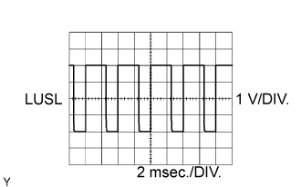
D98-78 (LUSL) - D98-109 (E1)
|
B - W-B
|
Diesel throttle duty signal
|
Engine warmed up, racing engine
|
Pulse generation
(See waveform 7)
|
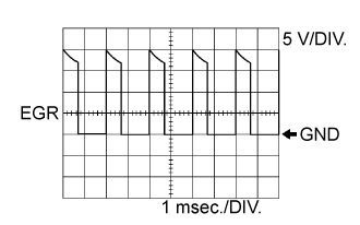
D98-83 (EGR) - D98-109 (E1)
|
B - W-B
|
Electric vacuum regulating valve assembly
|
Ignition switch ON
|
Pulse generation
(See waveform 9)
|
D98-101 (EGRC) - D98-109 (E1)
|
W - W-B
|
Vacuum switching valve (for EGR Cut)
|
Ignition switch ON, EGR cut (accelerator pedal fully depressed)
|
0 to 1.5 V
|
D98-118 (EGLS) - D98-92 (EEGL)
|
P - Y
|
EGR valve position sensor
|
Ignition switch ON
|
0.6 to 1.4 V
|
D98-92 (EEGL) - D98-75 (VC)
|
Y - L
|
EGR valve position sensor
|
Ignition switch ON
|
4.5 to 5.5 V
|
D98-106 (ECBV) - D98-109 (E1)
|
R - W-B
|
Vacuum switching valve (for EGR bypass valve)
|
Vacuum switching valve assembly (for EGR bypass valve) on
|
0 to 1.5 V
|
Vacuum switching valve assembly (for EGR bypass valve) off
|
11 to 14 V
|
D98-58 (GREL) - D98-109 (E1)
|
G - W-B
|
GLOW relay
|
Cranking
|
11 to 14 V
|
Idling
|
0 to 1.5 V
|
D98-108 (SCV) - D98-45 (E01)
|
W - W-B
|
Vacuum switching valve (for No. 1 swirl control valve)
|
Idling
|
0 to 1.5 V
|
Engine speed 2600 rpm or more
|
11 to 14 V
|
B72-59 (RTHW) - D98-74 (E2)
|
L - Y
|
Engine coolant temperature (radiator) sensor
|
Idling, engine coolant temperature (radiator) at -20 to 80°C (-4° to 176°F)
|
0.5 to 4.5 V
|
B72-49 (RFC) - D98-109 (E1)
|
LG - W-B
|
No. 1 Cooling Fan ECU
|
No. 1 cooling fan operating
|
Pulse generation
(See waveform 10)
|
B72-48 (RFC2) - D98-109 (E1)
|
P - W-B
|
No. 2 Cooling Fan ECU
|
No. 2 cooling fan operating
|
Pulse generation
(See waveform 10)
|
D98-38 (NSW)*2 - D98-45 (E01)
|
B - W-B
|
Park/neutral position switch assembly
|
Ignition switch ON, shift lever in P or N
|
Below 3 V
|
Ignition switch ON, shift lever not in P and N
|
11 to 14 V
|
B72-6 (CANL) - D98-109 (E1)
|
W - W-B
|
CAN communication line
|
Ignition switch ON
|
Pulse generation
(See waveform 11)
|
B72-7 (CANH) - D98-109 (E1)
|
B - W-B
|
CAN communication line
|
Ignition switch ON
|
Pulse generation
(See waveform 12)
|
D98-63 (CAN-)*2 - D98-109 (E1)
|
Y - W-B
|
CAN communication line
|
Ignition switch ON
|
Pulse generation
(See waveform 11)
|
D98-40 (CAN+)*2 - D98-109 (E1)
|
L - W-B
|
CAN communication line
|
Ignition switch ON
|
Pulse generation
(See waveform 12)
|