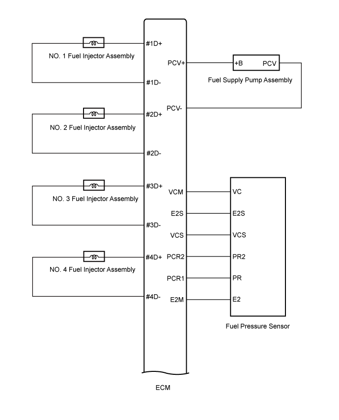
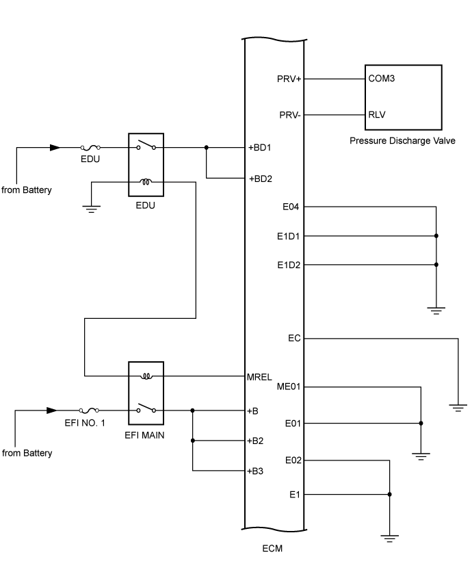
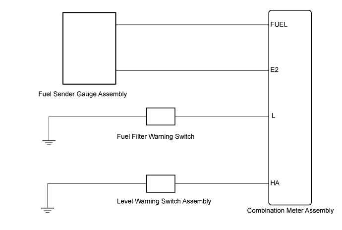
SYSTEM DIAGRAM
System information · Vehicles built from Jan 2017
| FUEL FLOW DIAGRAM |
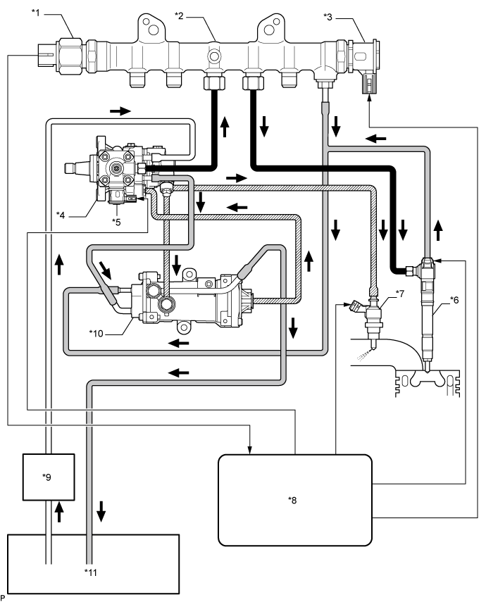

| *1 |
Fuel Pressure Sensor |
*2 |
Common Rail Assembly |
| *3 |
Pressure Discharge Valve |
*4 |
Fuel Supply Pump Assembly |
| *5 |
Pre-Stroke Control Valve |
*6 |
Injector Assembly |
| *7 |
Exhaust Fuel Addition Injector Assembly |
*8 |
ECM |
| *9 |
Fuel Filter Assembly |
*10 |
Fuel Filter Assembly(for Cylinder Block Side) |
| *11 |
Fuel Tank Assembly |
- |
- |
 |
High Pressure Fuel Line |
 |
Return Fuel Line |
 |
Suction Fuel Line |
 |
Pressurized Fuel Line |
| FUEL SYSTEM WIRING DIAGRAM |
By storing fuel at high pressure, the common rail system provides high pressure fuel injection.